Phase shift inverter, X-ray high-voltage device using same, X-ray CT device, and X-ray imaging device

a technology of phase shift inverter and x-ray high-voltage device, which is applied in the direction of material analysis using wave/particle radiation, instruments, nuclear engineering, etc., can solve the problems of large size and complicated control system, and achieve the effects of low cost, high reliability and weight saving

Inactive Publication Date: 2013-11-19
HITACHI LTD
View PDF6 Cites 123 Cited by
  • Summary
  • Abstract
  • Description
  • Claims
  • Application Information

AI Technical Summary

Benefits of technology

[0027]According to the present invention, it is not necessary to conduct current measurement in proximity to the semiconductor switches, allowing a single unit to simultaneously control both the power and frequency, thereby achieving downsizing, weight saving, price reduction, and high reliability. Furthermore, the present invention allows ZCS to be achieved, thereby reducing the switching loss.

Problems solved by technology

However, in this conventional apparatus, the control system is complicated and large in size, and thus the patent document 1 discloses a technique for implementing both functions by a single inverter circuit.

Method used


Image

  • Phase shift inverter, X-ray high-voltage device using same, X-ray CT device, and X-ray imaging device
  • Phase shift inverter, X-ray high-voltage device using same, X-ray CT device, and X-ray imaging device
  • Phase shift inverter, X-ray high-voltage device using same, X-ray CT device, and X-ray imaging device

Examples


first embodiment

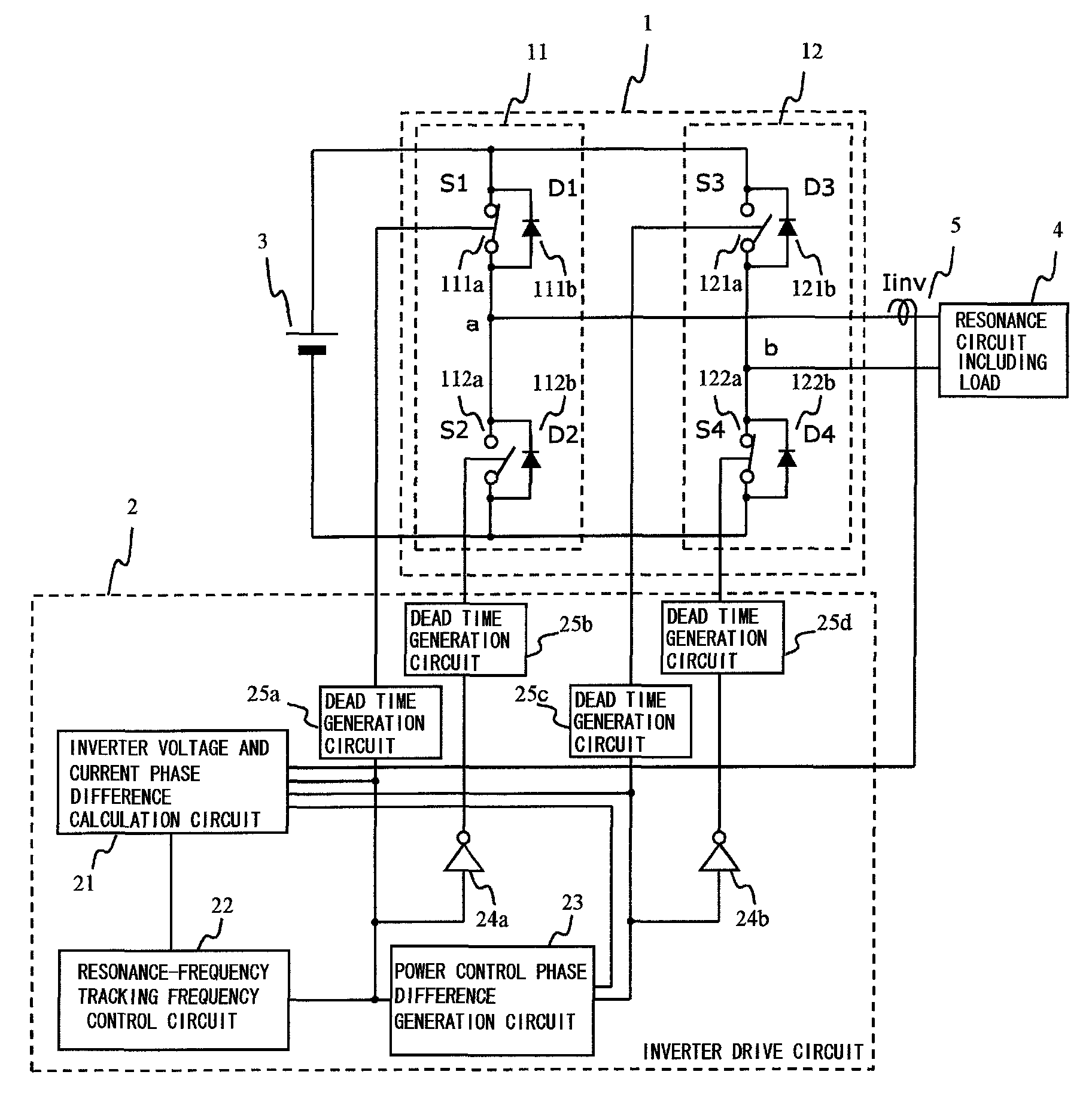
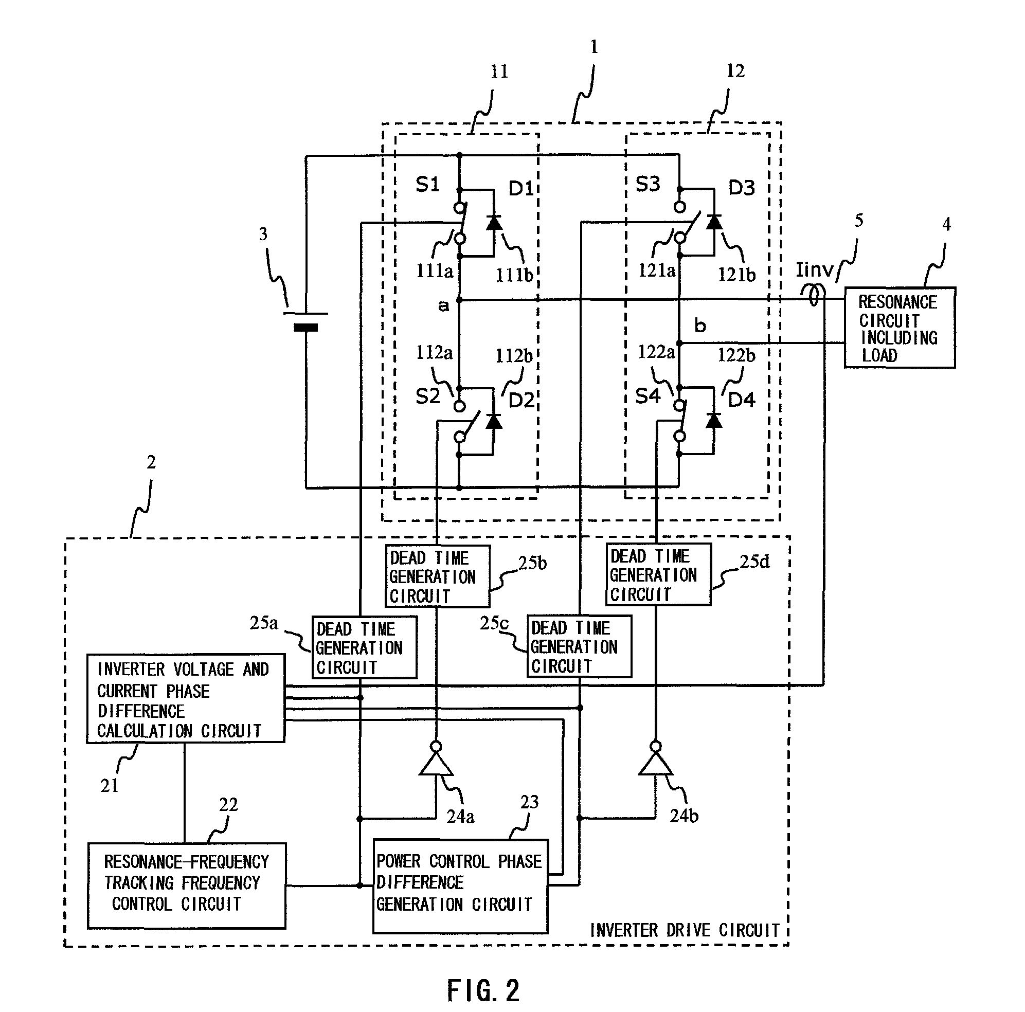
[0049]FIG. 2 is a schematic block diagram showing the phase shift inverter circuit and FIG. 3(a) and FIG. 3(b) illustrate waveforms such as driving signals thereof.

[0050]The inverter circuit of the first embodiment includes an inverter circuit part 1 and an inverter drive circuit part 2. The inverter circuit part 1 is connected to a DC power source 3. The output terminals a and b in the inverter circuit part 1 are connected to the resonance circuit 3 including load.

[0051]The inverter circuit part 1 has a configuration where the arm circuits 11 and 12 are connected in parallel. The arm circuit 11 is a circuit where the semiconductor switches (S1, S2) 111a and 112a are serially connected, the respective switches being inversely connected in parallel with the diodes (D1, D2) 111b and 112b. The arm circuit 12 is a circuit where the semiconductor switches (S3, S4) 121a and 122a are serially connected, the respective switches being inversely connected in parallel with the diodes (D3, D4)...

seventh embodiment

[0110]The X-ray high voltage generator 7 is a system for supplying tube voltage and tube current to be provided to the X-ray tube 8, and this system uses the X-ray high voltage generator 7 according to the The data collector 307 is a system for converting X-rays detected by the X-ray detector 306 into predetermined electrical signals. The gantry controller 308 is a system for controlling the rotation of the rotating disk 302. The bed controller 309 is a system for controlling vertical movement and horizontal movement (movement in the rotating axis direction of the rotating disk 302) of the bed 305.

[0111]The console 320 is provided with an input unit 321, an image operation unit 322, a display unit 325, a storage unit 323, and a system control unit 324. The input unit 321 is a system for inputting a name of the test subject, date and time of the test, an imaging condition, and the like, and specifically, it may be a keyboard, a pointing device, or the like. The image operation unit ...


PUM


Abstract

An inverter circuit allowing a single drive circuit to perform both tracking control for tracking resonance frequency fluctuations caused by load fluctuations, and power control, thereby reducing switching loss. An inverter drive circuit part obtains a phase difference between output current and output voltage directed to a load circuit connected to a midpoint of two arm circuits of the inverter circuit, and controls a phase of the driving signal directed to each semiconductor switch such that the phase difference becomes zero or a predetermined value, enabling an operating frequency of the inverter circuit part to track a resonance frequency of the load circuit, and enabling a current phase to be delayed with respect to a voltage phase, thereby achieving ZCS. Since the phase difference is used, an auxiliary circuit is not necessary for measuring a current value in proximity to the semiconductor switches.

Description

TECHNICAL FIELD[0001]The present invention relates to a phase shift inverter circuit driven at a frequency which tracks a resonance frequency caused by changes in load, and an X-ray high voltage generator using the phase shift inverter circuit.BACKGROUND ART[0002]A technique of the inverter circuit which is driven at a high frequency is applied to various equipment such as an induction heating cooking device which inductively heats a metallic pan using a high-frequency magnetic field, an industrial induction heating apparatus aiming at dissolution or quenching of metal, and an X-ray imaging apparatus and an X-ray CT (Computer Tomography) apparatus for a medical / industrial use to acquire an X-ray perspective image and a tomographic image of a test subject.[0003]Typically, an inductor or an X-ray tube is considered as a load of the inverter circuit in those fields as described above, and its impedance may be largely different or change according to setup conditions of voltage and curr...

Claims


Application Information

Patent Timeline
Patent Type & Authority Patents(United States)
IPC IPC(8): H05G1/10
CPCH02M7/53871H05G1/20H02M2007/4815Y02B70/1441Y02B70/10H02M7/4815
Inventor OGAWA, MINAANDO, ITARUOHISHI, KIYOSHISHINDO, SHOUTARO
Owner HITACHI LTD
Why Eureka
Try Eureka