Control apparatus for multi-phase rotary machine and electric power steering system

a control apparatus and multi-phase technology, applied in the direction of electric generator control, dynamo-electric converter control, dynamo-electric gear control, etc., can solve the problem that the control apparatus cannot continue to drive the rotary machin

Active Publication Date: 2011-03-31
DENSO CORP
View PDF4 Cites 113 Cited by
  • Summary
  • Abstract
  • Description
  • Claims
  • Application Information

AI Technical Summary

Benefits of technology

[0008]It is an object of the present invention to provide a control apparatus for a multi-phase rotary machine which can, when an ON failure occurred in one of switching elements or when a winding of a rotary machine and a power source are short-circuited, suppresses the influence of a brake torque which is generated in a failure system or the influence of a change of an output of the failure system from being exerted on the driving of the rotary machine so that the stable driving of the rotary machine can be continued.
[0010]In one aspect, the control unit stops driving the rotary machine, which is performed by the failure system, by controlling all of the high-side switching element and the low-side switching element of each leg in the failure system into OFF states, respectively. The control unit continues to drive the rotary machine by a no-failure system, which is one of the plurality of systems and has no short-circuit failure. The control unit controls the high-side switching element and the low-side switching element of each leg in a no-failure system of the plurality of systems such that an output is cancelled or an influence of the output exerted on the driving of the rotary machine is reduced, the output being generated when driving the rotary machine by the first system is stopped and resistive to driving of the rotary machine.
[0011]In another aspect, the control unit continues to drive the rotary machine by a no-failure leg, which has no short-circuiting failure, in the failure system, and by a no-failure system, which is one of the plurality of systems and has no short-circuiting failure. The control unit controls the high-side switching element and the low-side switching element of each leg in the no-failure system, such that a variation in an output of the failure system is cancelled or an influence of the variation in the output on the driving of the rotary machine is reduced, the variation in the output of the failure system being caused by driving the rotary machine by only the non-failure leg of the failure system.

Problems solved by technology

However, when the ON failure (a failure in which a switching element is always held in a conductive state) occurs in one of the switching elements, the control apparatus does not continue to drive the rotary machine.
When the ON failure occurred in one of the switching elements, a coil in each phase of the rotary machine and a power source or a ground become conductive with each other.

Method used


Image

  • Control apparatus for multi-phase rotary machine and electric power steering system
  • Control apparatus for multi-phase rotary machine and electric power steering system
  • Control apparatus for multi-phase rotary machine and electric power steering system

Examples


first embodiment

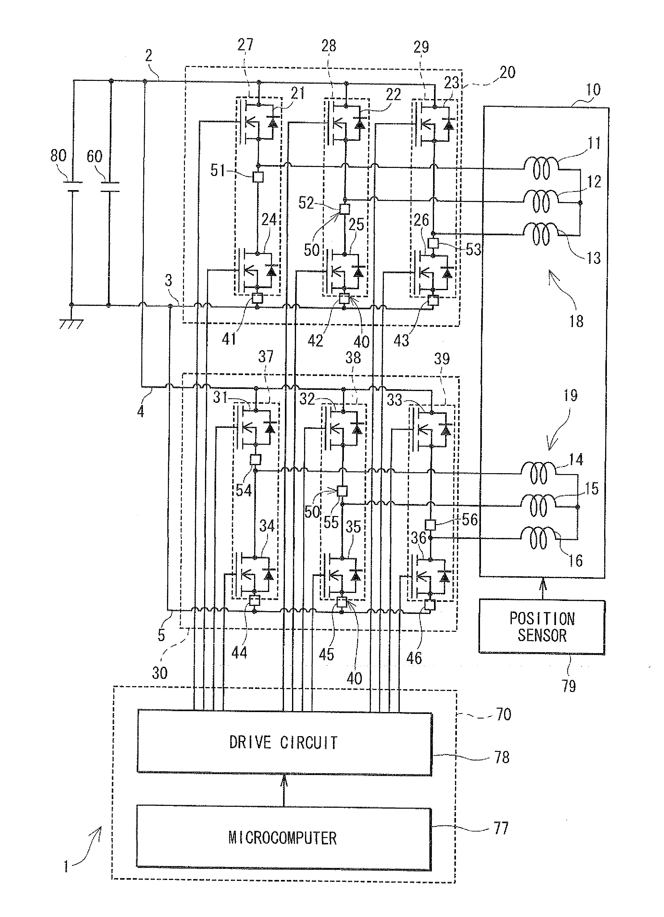
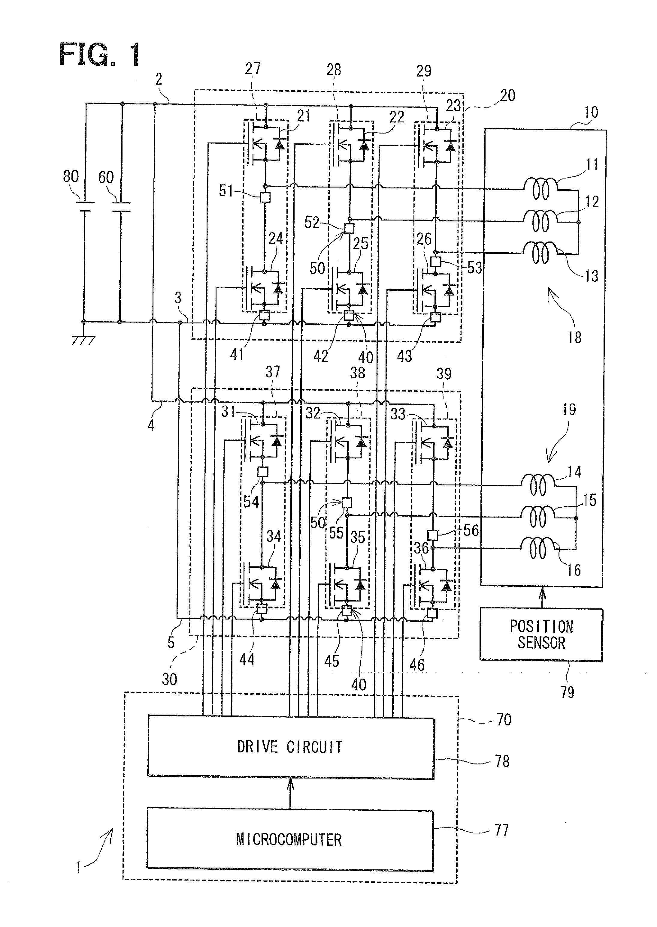
[0037]As shown in FIG. 1, a control apparatus 1 is provided to perform a drive control of an electric motor 10, which is a rotary machine. The control apparatus 1 is adopted, for example, for an electric power steering system which power-assists a steering operation of a vehicle by the motor 10.

[0038]The motor 10 is a three-phase brushless motor and includes a rotor and a stator (not shown). The rotor is a cylindrical body, mounts permanent magnets on its surface, and has magnetic poles. The stator houses the rotor therein and rotatably supports the rotor. The stator includes protruding portions which protrude radially inward at an interval of predetermined angle in the circumferential direction. A U1 coil 11, a V1 coil 12, a W1 coil 13, a U2 coil 14, a V2 coil 15 and a W2 coil 16 are wound around these protruding portions. The U1 coil 11, the V1 coil 12 and the W1 coil 13 form a U-phase coil, a V-phase coil and a W-phase coil of a first winding set 18, respectively. The U2 coil 14,...

second embodiment

[0106]The control apparatus 1 according to the second embodiment partially differs from the first embodiment with respect to the manner of controlling the non-failure system by the control unit 70 after the short-circuiting failure occurred.

[0107]In the first embodiment, when the short-circuiting failure occurred because of the occurrence of the ON failure in the U high-side FET 21, for example, the control unit 70, upon inputting of the failure flag to the control unit 70, adds the current Iq1 to the q-axis command current Iq* to form the corrected q-axis command current Iq** and controls the second inverter unit 30 based on the corrected q-axis command current Iq** (FIG. 8B). To the contrary, as shown in FIG. 12, the second embodiment is characterized in that, when the short-circuiting failure occurred, the control unit 70, upon inputting of the failure flag to the control unit 70, adds the current Iq1 and the current Iq2 to the q-axis command current Iq* to form the corrected q-a...

third embodiment

[0111]The control apparatus 1 according to the third embodiment differs from the first embodiment with respect to the manner of controlling the failure system and the manner of controlling the non-failure system by the control unit 70 after the short-circuiting failure occurred.

[0112]In the first embodiment, when the control unit 70 determines that the ON failure occurred in one of the FETs 21 to 26, 31 to 36, the control unit 70 performs a control such that all FETs (FETs 21 to 26 or the FETs 31 to 36) in the system (first system or second system) which includes the failure FET are brought into the OFF state, and stops the driving of the motor 10 by the failure system including the failure FET. To the contrary, the third embodiment is characterized in that, when the control unit 70 determines that the ON failure occurred in one of the FETs 21 to 26, 31 to 36, the control unit 70 performs a control such that the driving of the motor 10 is continued also by the failure system, which ...


PUM


Abstract

A control apparatus for a multi-phase rotary machine includes a control unit and a plurality of power supply systems including respective inverter units. When a short-circuiting failure occurs in one of the systems due to an ON-failure in any one of FETs in an inverter unit of the failure system, the control unit stops driving of the rotary machine by bringing all the FETs in the failure system into the OFF state. The control unit controls FETs of the non-failure system such that a brake torque generated in the failure system is cancelled or the influence of the brake torque exerted on the driving of the motor is reduced.

Description

CROSS REFERENCE TO RELATED APPLICATION[0001]This application is based on and incorporates herein by reference Japanese patent application No. 2009-227973 filed on Sep. 30, 2009.FIELD OF THE INVENTION[0002]The present invention relates to a control apparatus for a multi-phase rotary machine and an electric power steering system using the control apparatus.BACKGROUND OF THE INVENTION[0003]A conventional control apparatus for a multi-phase rotary machine controls a multi-phase rotary machine by controlling ON / OFF switching of a plurality of switching elements. In such a control apparatus for a rotary machine, it is proposed by the following patent documents to allow the rotary machine to continue its operation even when a failure occurred in a part of the switching element.[0004]Patent document 1: US 2007 / 0176577 A1 (WO 2005 / 091488 A1)[0005]Patent document 2: JP 2005-304119A[0006]In patent document 1, when the OFF failure (a failure in which a switching element is always held in a non-...

Claims


Application Information

Patent Timeline
Patent Type & Authority Applications(United States)
IPC IPC(8): H02P6/12H02P27/04H02P21/00H02P25/22H02P27/08
CPCB62D5/0403B62D5/0484B62D5/0487G01R31/025H02P29/022H02H7/1225H02P6/165H02P25/22G01R31/42G01R31/52H02P21/00H02P6/17H02P29/032
Inventor SUZUKI, TAKASHI
Owner DENSO CORP
Why Eureka
Try Eureka