Electronic parking braking method

An electronic parking brake and parking technology, applied in the directions of brakes, brake transmission devices, hydraulic brake transmission devices, etc., can solve the problem of high technical requirements of drivers, poor use effect, low adhesion coefficient road surfaces and slope starting. Problems such as difficult operation, to achieve the effect of easy operation, low cost, simple and reasonable structure

Active Publication Date: 2011-05-11
XIAN KING TRUCK ELECTRON
View PDF7 Cites 29 Cited by
  • Summary
  • Abstract
  • Description
  • Claims
  • Application Information

AI Technical Summary

Problems solved by technology
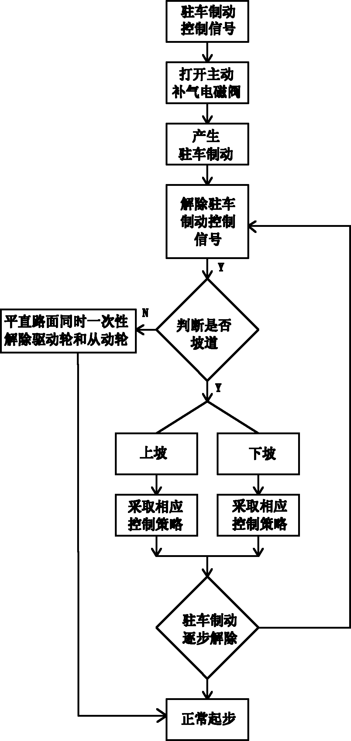
[0003] The technical problem to be solved by the present invention is to provide an electronic parking brake method with reasonable design, convenient wiring, low investment cost, easy operation, high intelligence and good effect , can effectively solve many practica

Method used


Image

  • Electronic parking braking method
  • Electronic parking braking method
  • Electronic parking braking method

Examples


Embodiment 1

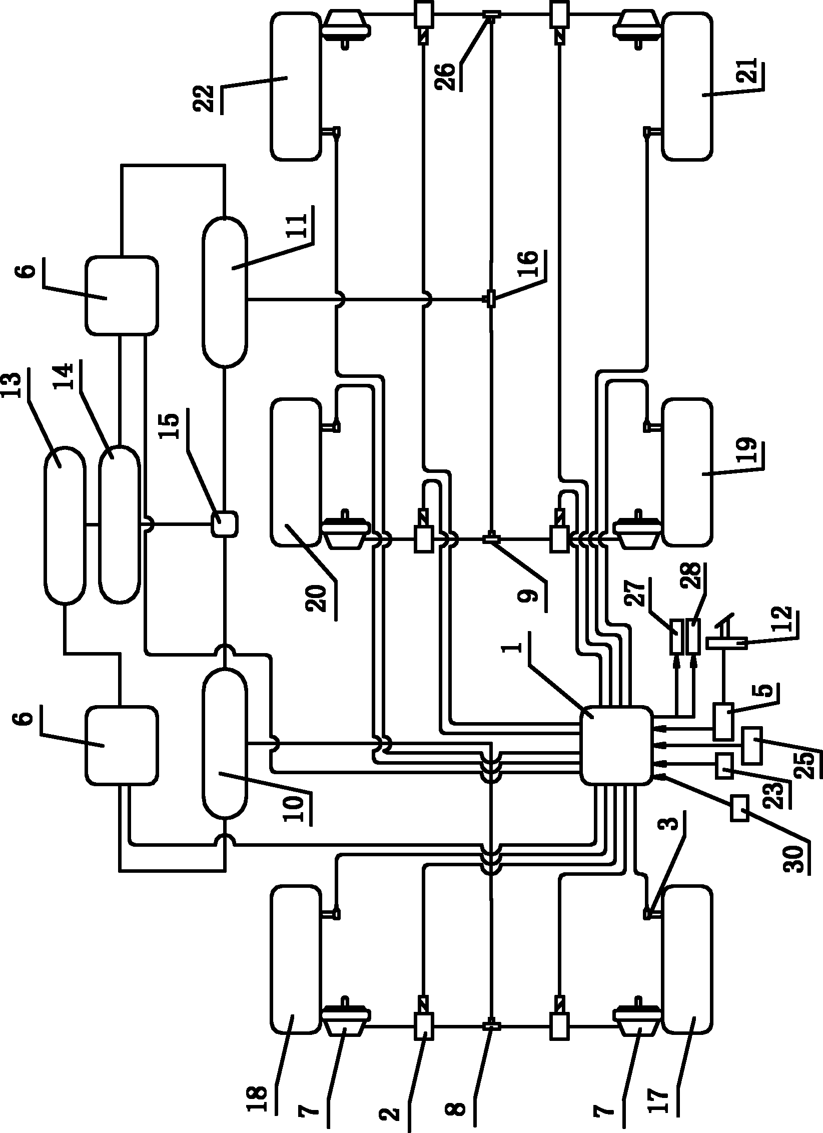
[0054] Such as figure 1 , figure 2 As shown, the electronic parking brake system used in the present invention includes a parking brake control unit 1, a plurality of wheel speed sensors 3 that detect the wheel speeds of the wheels installed on the vehicle body in real time, and a plurality of The parking brake control unit 1 is connected to the ABS electromagnetic regulating valve 2 that adjusts the braking force of each wheel accordingly, the two-way one-way solenoid valve, the pedal displacement sensor 5 that detects the displacement of the accelerator pedal 12 in real time, and the gas storage cylinder. The active gas supplement solenoid valve 6 connected with the parking brake switch 25 connected with the parking brake control unit 1, the pedal displacement sensor 5 and the wheel speed sensor 3 are connected with the parking brake control unit 1. The air storage tank communicates with the main brake valve 15 and the active air supply solenoid valve 6 through the brake a...

Embodiment 2

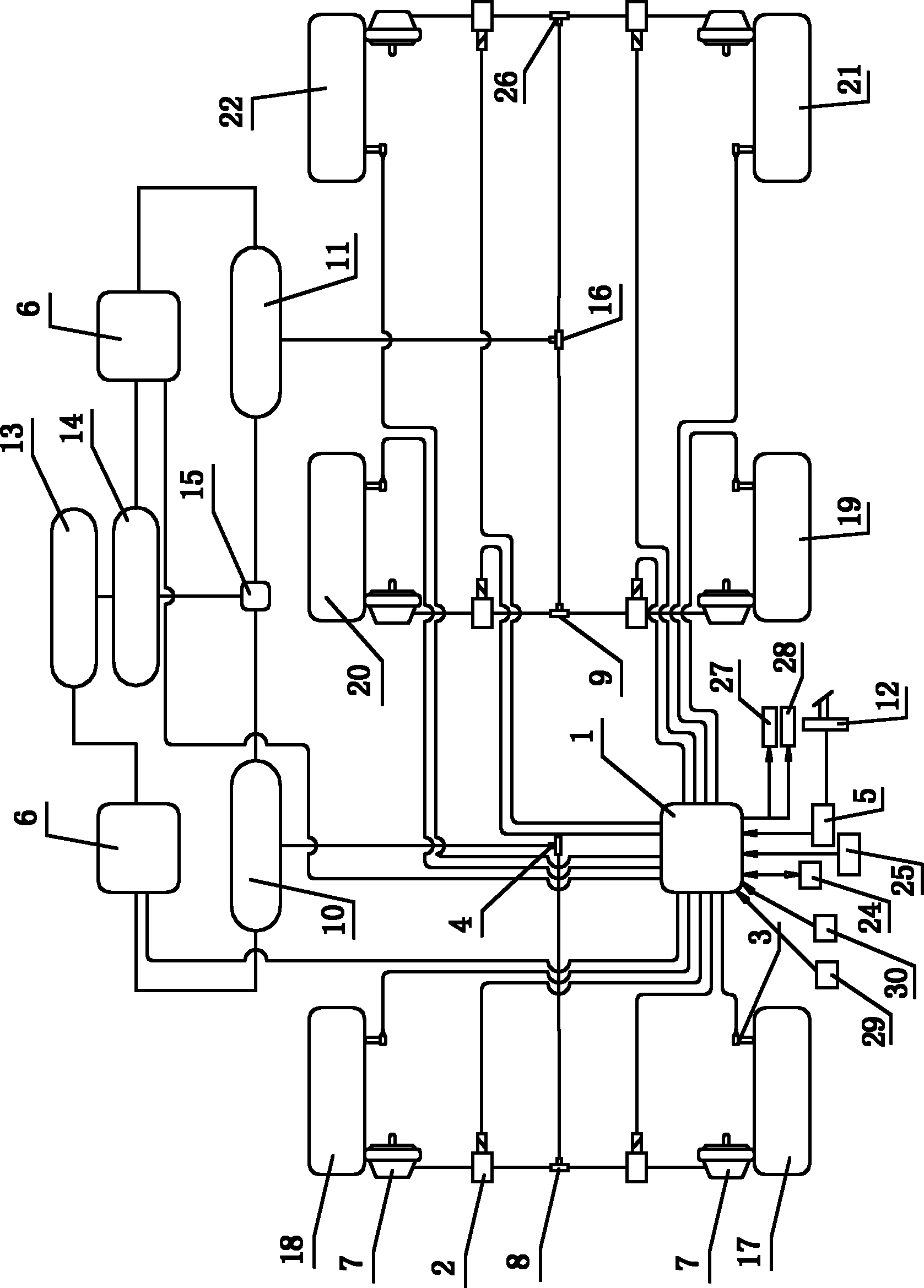
[0083] In this embodiment, the electronic parking brake system used is different from Embodiment 1 in that: the parking brake control unit 1 is connected to the vehicle local area network 24 installed inside the vehicle body through the CAN communication bus, that is, through The vehicle local area network 24 acquires the engine speed signal; at the same time, the electronic parking brake system also includes a vehicle body tilt angle detection unit that is arranged on the center of mass of the vehicle body of the controlled vehicle and detects the tilt direction of the vehicle body of the controlled vehicle in real time 29. The vehicle body inclination angle detection unit 29 is connected to the parking brake control unit 1, and in step 202, the parking brake control unit 1 invokes the slope judging module according to the vehicle body inclination angle detection unit 29 The actual inclination angle of the vehicle body can be used to determine the condition of the road section...


PUM


Abstract

The invention discloses an electronic parking braking method. The method comprises the following steps of: first, parking braking, namely transferring prestored air pressure in an air reservoir to brake chambers of each wheel by controlling an active air supply electromagnetic valve to realize the parking braking; and second, releasing braking, namely when a road section is a straight road surface, simultaneously releasing a drive wheel and a driven wheel of a controlled vehicle once; and when the road section is a downhill road section or an uphill road section, adopting a corresponding control strategy according to the rotating situations of each wheel of the vehicle, and releasing the air pressure in the brake chambers of each wheel of the controlled vehicle separately by utilizing a pressure maintaining effect of an antilock brake system (ABS) electromagnetic regulating valve. The electronic parking braking method has a reasonable design, low investment cost, high intelligence degree and good use effect, is convenient to operate, and solves the practical problems of high technical requirements on drivers, brake force transfer gap of mechanical system, great difficulties in starting operation on low-adhesion coefficient road surface and ramp, poor use effect and the like in a conventional mechanical parking braking system.

Description

technical field [0001] The invention belongs to the technical field of automobile braking, and in particular relates to an electronic parking braking method. Background technique [0002] With the rapid development of urban roads and the continuous improvement of vehicle driving speed, the driving speed of vehicles is getting higher and higher, coupled with the continuous increase of urban population and the continuous increase of car ownership, all make the driver's control over the operation of vehicles become particularly important. At present, the traditional parking brake system used requires the driver to continue to depress the brake pedal after releasing the parking brake to prevent the vehicle from sliding backwards, but at the same time it needs to depress the accelerator pedal to increase the engine speed To obtain the drive torque, so the driver's requirements are relatively high. In addition, the traditional mechanical parking brake (hand brake), especially wh...

Claims


Application Information

Patent Timeline
IPC IPC(8): B60W30/06B60W10/18B60W10/06B60W40/08B60W40/10B60T13/68B60T11/26B60T8/171
Inventor 韩琳王小峰
Owner XIAN KING TRUCK ELECTRON
Why Eureka
Try Eureka