

Power Tool
a power tool and power technology, applied in the field of power tools, can solve problems such as difficulty in disposing the board at another position, and achieve the effect of improving the method of attaching the switching elements
- Summary
- Abstract
- Description
- Claims
- Application Information
AI Technical Summary
Benefits of technology
Problems solved by technology
Method used
Image

Examples
first embodiment
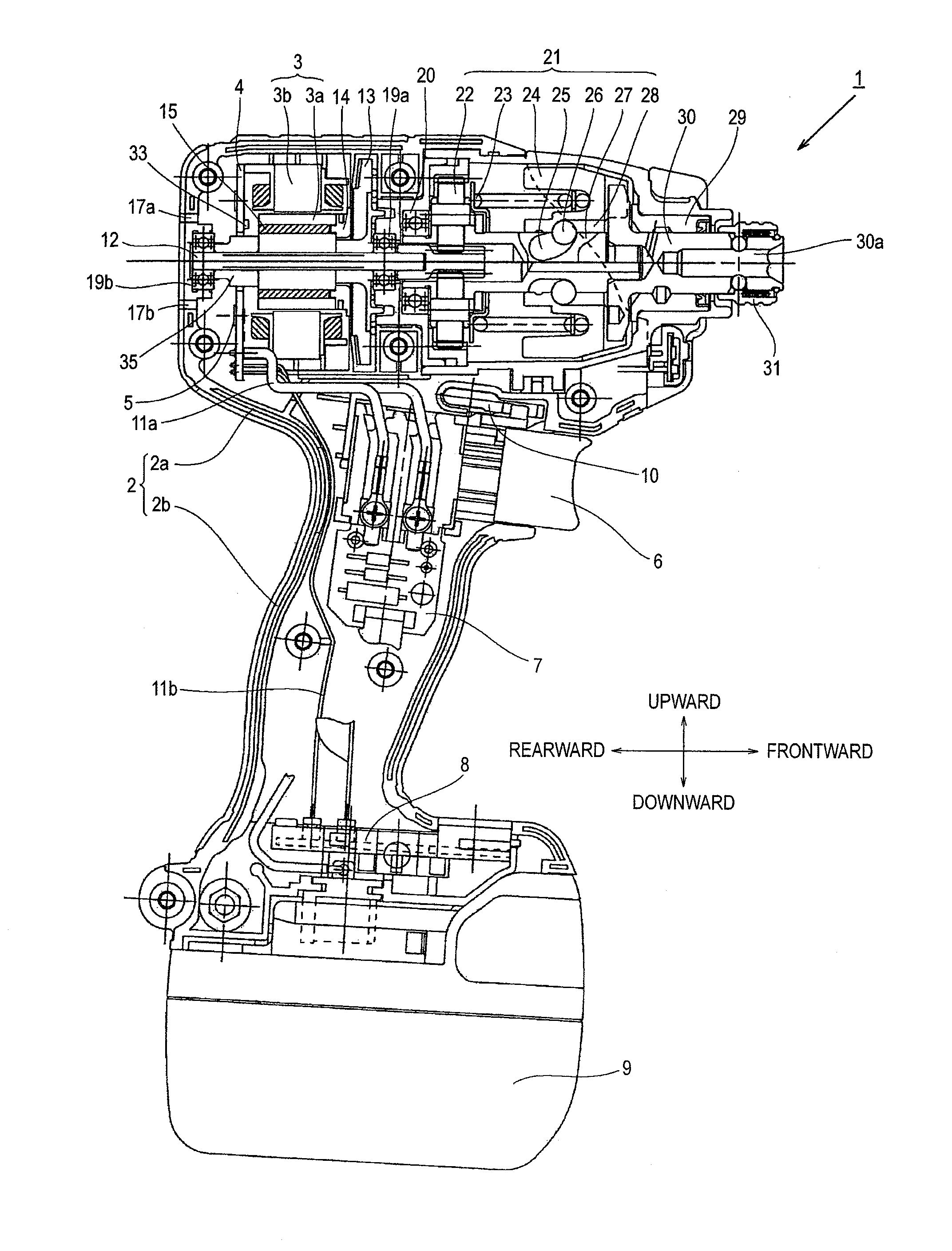
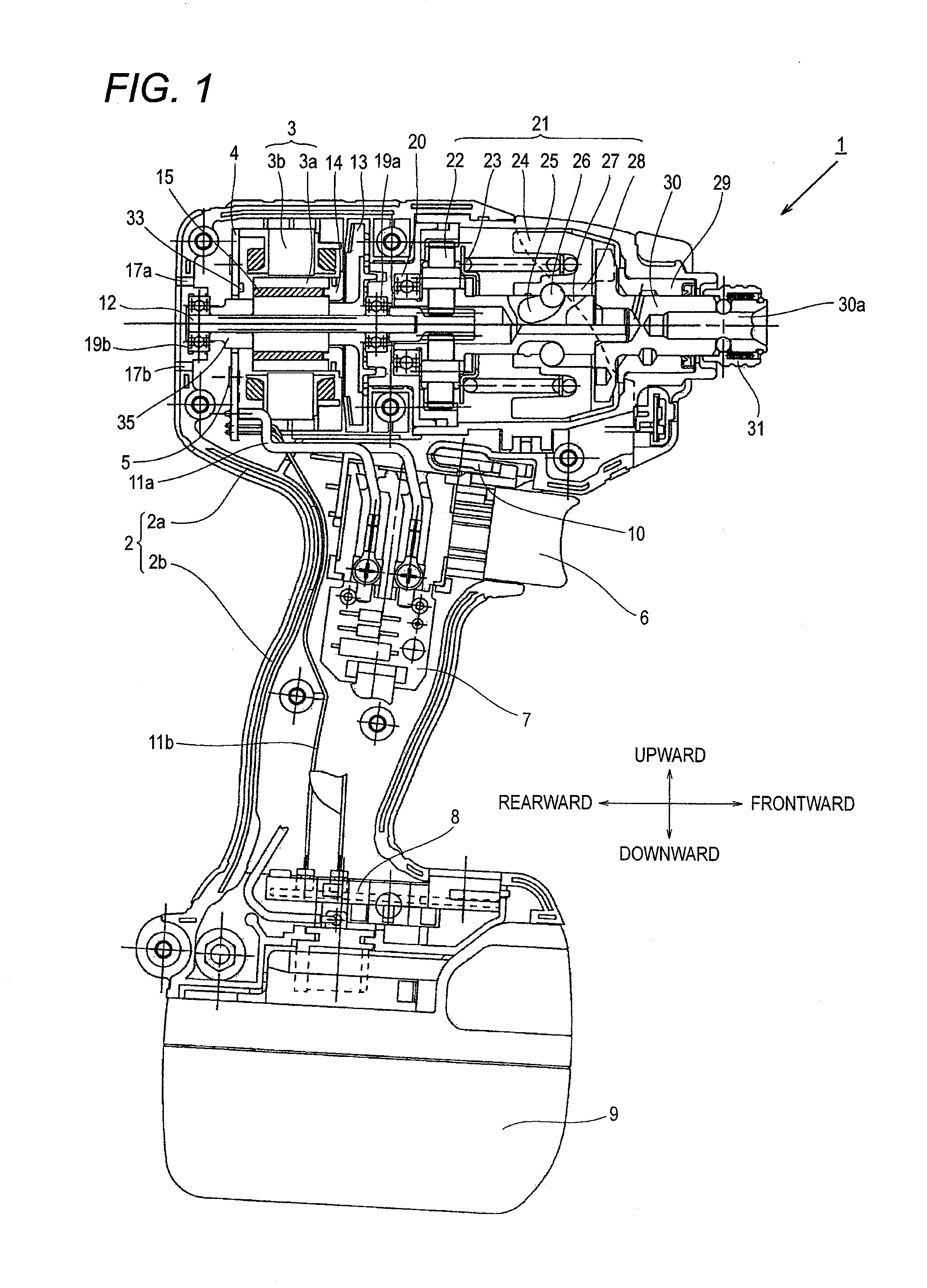
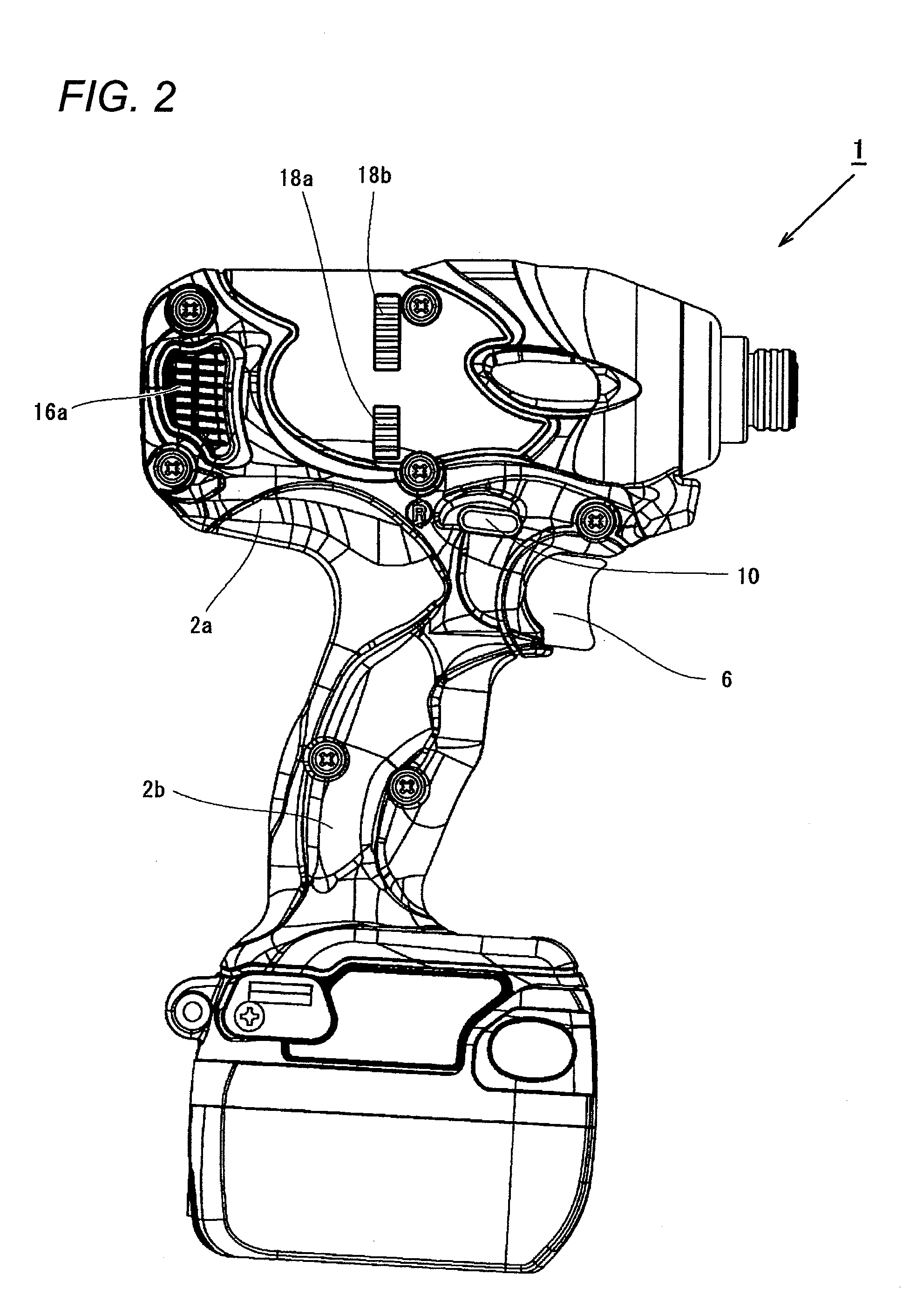
[0046]Hereinafter, embodiments according to the invention will be explained based on drawings. In the following explanation, the upper, lower, front and rear directions coincide with the respective directions shown in FIG. 1 except for FIGS. 6A and 6B. FIG. 1 is a diagram showing the inner structure of an impact driver 1 according to the power tool of the invention. The impact driver 1 drives a rotary switching mechanism 21 based on a chargeable battery 9 acting as a power supply and a motor 3 acting as a driving source to apply a rotation power and a striking power to an anvil 30 acting as an output shaft to thereby intermittently apply a rotary striking force to a not-shown tip end tool such as a driver bit held by an attachment hole 30a covered by a sleeve 31, whereby a processing such as a screw fastening or a bolt fastening is performed.
[0047]The brushless DC type motor 3 is housed within the cylindrical body portion 2a of a housing 2. The rotation shaft 12 of the motor 3 is ro...
fourth embodiment
[0083]Next an example of mounting the switching element 105 on the circuit board will be explained with reference to FIGS. 15 to 18. FIG. 15 is a diagram for explaining the arrangement of a switching element 105 according to the invention and is a diagram showing an inverter circuit board 104 seen from the rear side. The inverter circuit board 104 has an almost circular shape which is almost same as the contour of the motor 3 and is provided at the center portion thereof with a hole 104a for passing a spacer 35 therethrough. Four screw holes 104b are formed at the periphery of the inverter circuit board 104 and the inverter circuit board 104 is fixed to the stator 3b by means of screws passed through the screw holes 104b. Six switching elements 105-1 to 105-6 each having the shape shown in FIGS. 12 to 14 are attached to the inverter circuit board 104 so as to surround the hole 104a. The six switching elements 105 are attached to the rear surface side (opposite side to the motor 3) o...
fifth embodiment
[0086]FIG. 16 is a diagram for explaining the arrangement of a switching element 115 according to the invention. This embodiment differs from FIG. 15 in a point that the diameter of a hole 114a at the center portion of an inverter circuit board 114 for passing the spacer 35 therethrough is large. Since the hole 114a is made large, the gap between the hole 114a and the spacer 35 becomes larger. Thus, the air sucked from the outside likely enters into the motor 3, so that advantageously the motor 3 can be cooled effectively.
[0087]Since the hole 114a is made large, the arrangement of the switching elements 115-1 to 115-6 is slightly changed. That is, although the arrangement of the switching elements 115-3 and 115-6 is same as that of FIG. 15, the switching elements 115-2, 115-5 are shifted to the outer periphery side in accordance with the enlargement of the hole 114a. This embodiment is same as FIG. 15 in a point that the switching elements 115-2 and 115-5 are disposed so as to be al...
PUM
 Abstract
Description
Claims
Application Information