Brushless motor

a brushless motor and motor body technology, applied in the direction of liquid fuel engines, magnetic circuit rotating parts, magnetic circuit shapes/forms/construction, etc., can solve the problems of increased under etching at the time of etching procedure, increased cost of the board "j", and brushless motor

Inactive Publication Date: 2001-10-02
CALSONIC KANSEI CORP
View PDF7 Cites 74 Cited by
  • Summary
  • Abstract
  • Description
  • Claims
  • Application Information

AI Technical Summary

Problems solved by technology

As a result, the copper foils of the wiring pattern have to have a thicker structure, that however causes an increased cost of the board "j" and thus that of the brushless motor "a".
Second, due to the same reason, the amount of under etching at the time of etching procedure is increased.
Considering this, the copper foils of the wiring pattern of the motor control circuit have to have a large width, that makes compactness of the motor c

Method used


Image

  • Brushless motor
  • Brushless motor
  • Brushless motor

Examples


first embodiment

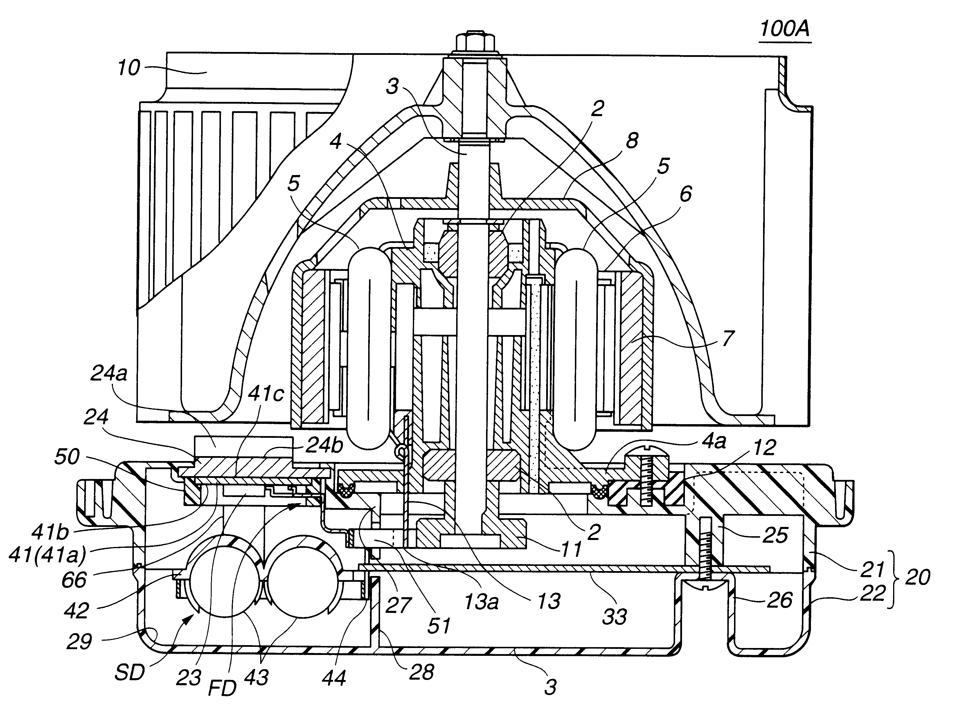
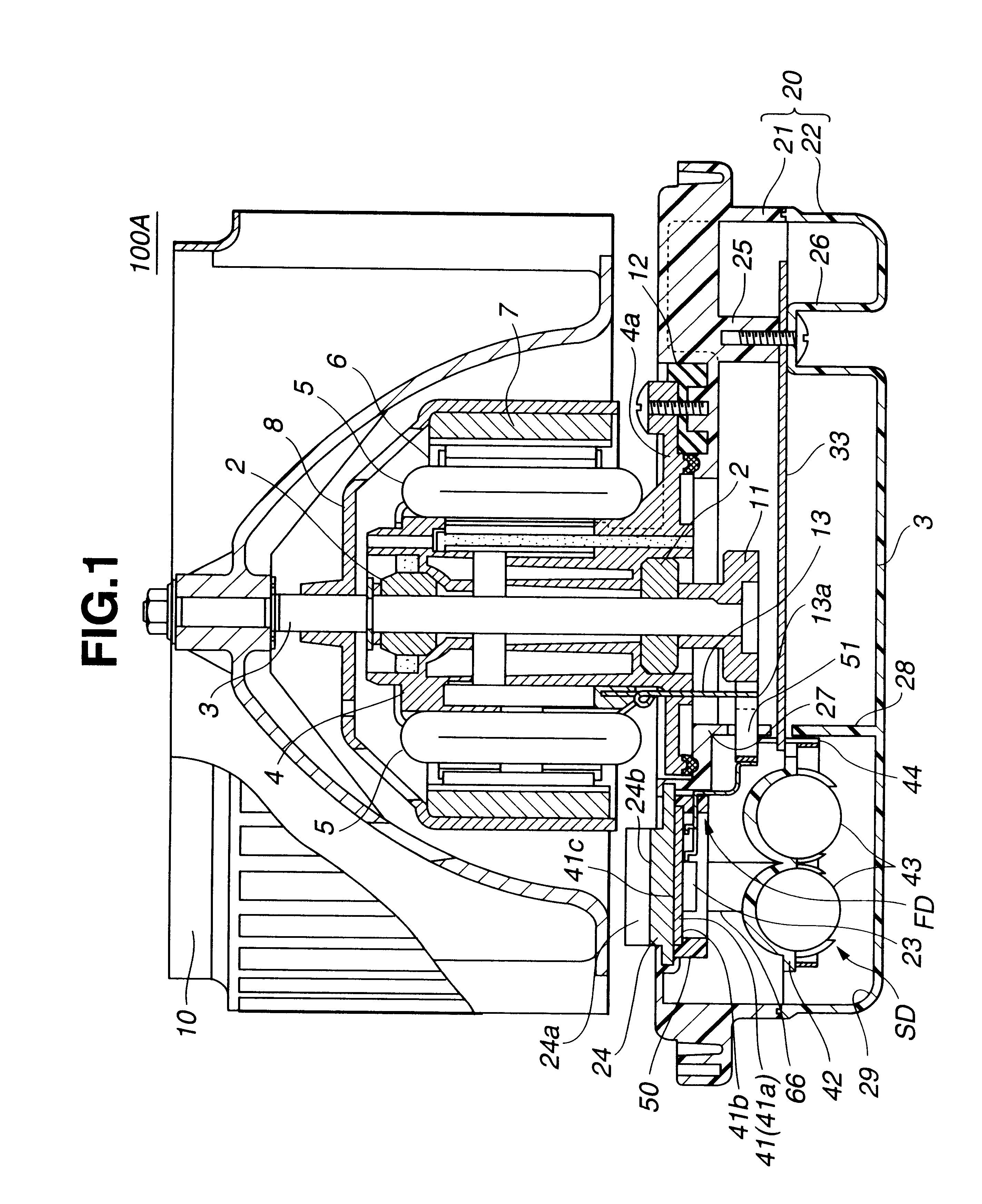
Referring to FIGS. 1 to 8, particularly FIG. 1, there is shown a brushless motor 100A which is the present invention.

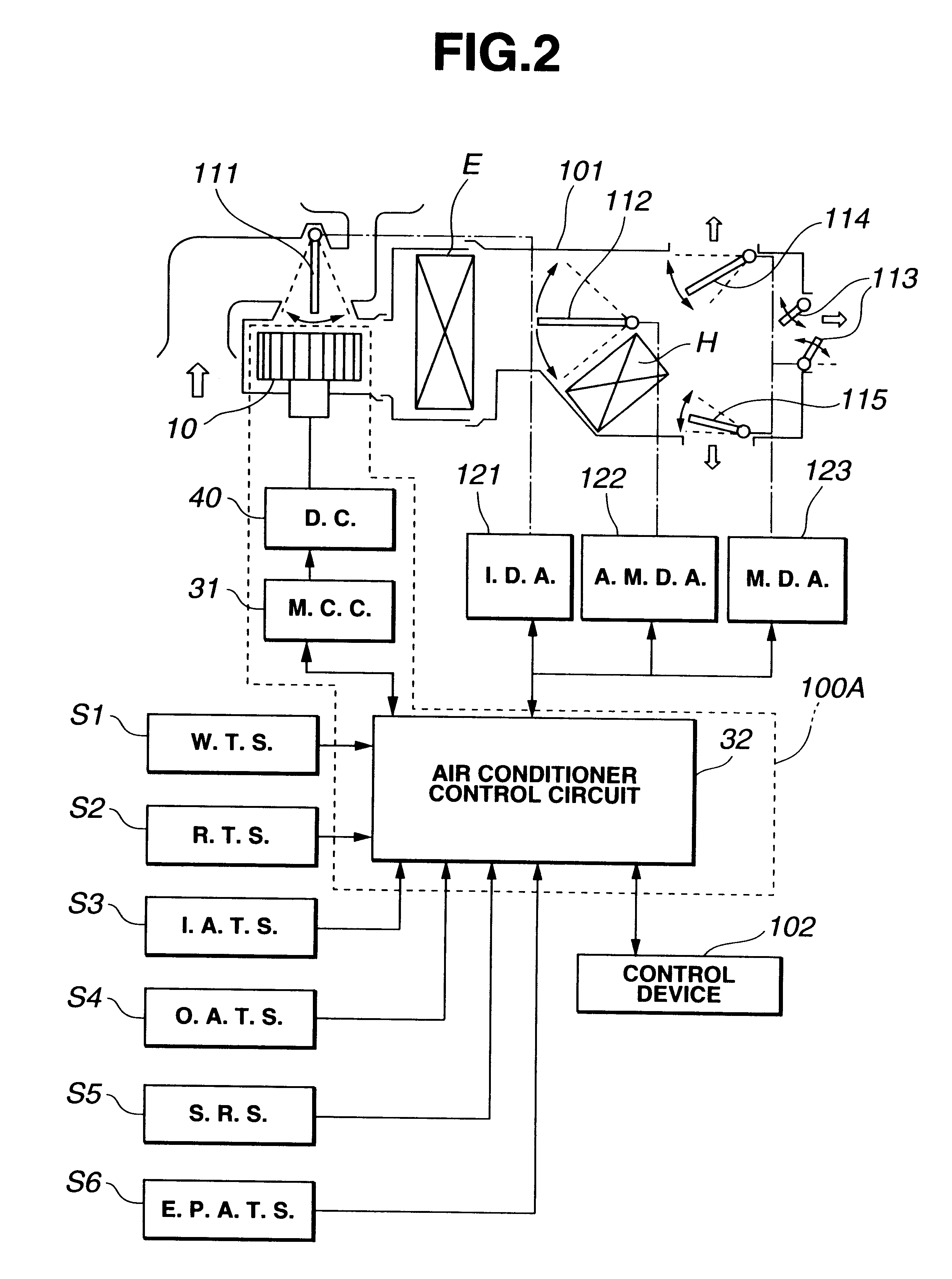
As is seen from FIG. 2, the brushless motor 100A can be used as a motor for driving a blower or scirocco fan 10 in an automotive air conditioner which will be described in detail hereinafter.

As is best shown in FIG. 1, the brushless motor 100A comprises a housing 4 by which a drive shaft 3 is rotatably held through upper and lower bearings 2. A stator 6 is disposed about the housing 4, which is equipped thereabout with a plurality of coils 5. A cup-shaped yoke 8 is fixed to the drive shaft 3 in a manner to surround the stator 6. A plurality of ferrite magnets 7 are mounted to an inner surface of the yoke 8 keeping a small space from the stator 6. The blower fan 10 is fixed to a leading end of the drive shaft 3, as shown. The housing 4 is mounted on an electric parts protecting case 20 through rubber pads 12. For this mounting, the housing 4 has a lower flange portion ...

second embodiment

Referring to FIGS. 9 to 17, particularly FIG. 9, there is shown a brushless motor 100B which is the present invention.

Since the brushless motor 100B of this embodiment is similar in construction to the above-mentioned brushless motor 100A of the first embodiment, detailed explanation will be directed to only parts and portions which are different from those of the first embodiment 100A. Substantially the same parts as those of the first embodiment 100A are denoted by the same numerals for ease of understanding.

As will be easily understood when comparing FIGS. 1 and 9, the lower part of the brushless motor 100B is different from that of the first embodiment 100A.

In the second embodiment 100B, within an electric parts protecting case 20, there are arranged a first drive circuit 220, a second drive circuit 230 and a control circuit 240. The first drive circuit 220 is provided with a plurality of switching elements 23 for switching the flow paths of current flowing through the coils 5 o...

third embodiment

Referring to FIGS. 18 to 23, particularly FIG. 18, there is shown a brushless motor 100C which is the present invention.

Since the brushless motor 100C of this third embodiment is similar in construction to the above-mentioned brushless motor 100A of the first embodiment, detailed explanation will be directed to only parts and portions which are different from those of the first embodiment 100A. Substantially the same parts as those of the first embodiment 100A are denoted by the same numerals for ease of understanding.

As will be easily understood when comparing FIGS. 1 and 18, the lower part of the brushless motor 100C is different from that of the first embodiment 100A.

In the third embodiment 100C, within an electric parts protecting case 20, there are installed first and second drive circuits 329 and 331. Like the above-mentioned second embodiment 100B, there is also arranged in the electric parts protecting case 20 a partition wall 332d by which the interior of the case 20 is par...


PUM


Abstract

A brushless motor comprising a housing; a drive shaft rotatably held by the housing; a stator disposed on said housing and having a plurality of coils which are arranged to surround the drive shaft; a yoke secured to the drive shaft to rotate therewith; a plurality of magnets that are held by the yoke in a manner to surround the stator keeping a given space therebetween; an electric parts protecting case on which the housing is mounted; a drive circuit installed in the case for energizing the coils of the stator, the drive circuit including a plurality of switching elements each changing the direction of electric current flowing in the corresponding coil of the stator; a control circuit installed in the case for controlling operation of the switching elements to adjust a rotation speed of the drive shaft; electric connectors for connecting the drive and control circuits; and a heat sink held by the case, the heat sink including a hidden portion exposed to an interior of the case and a plurality of heat radiation fins exposed to the outside of the case, the hidden portion having the switching elements attached thereto. The drive circuit and control circuit are arranged on respective substitutes which are arranged at different positions in the electric parts protecting case. The drive and control circuits are connected through electric connectors.

Description

1. Field of the InventionThe present invention relates in general to electric motors and more particularly to brushless motors suitable for driving a blower used in an automotive air conditioner.2. Description of the Prior ArtIn order to clarify the task of the present invention, one conventional brushless motor will be described with reference to FIGS. 31 and 32 of the accompanying drawings.In FIG. 31, there is shown the conventional brushless motor "a" that is used for driving a blower fan "h" of an automotive air conditioner The brushless motor "a" comprises a housing "d" by which a drive shaft "c" is rotatably held through upperand lower bearings "b". A stator "e" is disposed about the housing "d". A cup-shaped yoke "g" is fixed to the drive shaft "c" in a manner to surround the stator "e". A plurality of ferrite magnets "f" are mounted to an inner surface of the yoke "g" keeping a small space from the stator "e". The blower fan "h" is fixed to a leading end of the drive shaft "...

Claims


Application Information

Patent Timeline
IPC IPC(8): H02K11/04H02K5/22
CPCH02K11/0073H02K5/225H02K11/33F04D25/0613F04D29/5813F04D25/068
Inventor SUNAGA, HIDEKIOBA, TAKESHIOHIRA, SHIGENORI
Owner CALSONIC KANSEI CORP
Why Eureka
Try Eureka