Brushless motor

a brushless motor and motor shaft technology, applied in the direction of synchronous machines, dynamo-electric components, mechanical energy handling, etc., can solve the problems of motor vibration, motor coming into contact with resolvers, and inability to ensure the accuracy of shafts b>4/b> attached to ball bearings b>2/b>, so as to increase the number of poles of resolver stators and increase the outside diameter of resolver stators.

Active Publication Date: 2006-10-12
NIPPON DENSAN CORP
View PDF3 Cites 81 Cited by
  • Summary
  • Abstract
  • Description
  • Claims
  • Application Information

AI Technical Summary

Benefits of technology

[0014] Further, in the resolver stator, a connection base is formed so as to radially project to the outside. The outermost peripheral face of the connection base is positioned on the outside of the inner peripheral surface of the bus bar. With the configuration, the outside diameter of the resolver stator can be increased, and the number of poles of the resolver stator can be increased.
[0015] In a pa

Problems solved by technology

As a result, when the distance between the ball bearings 2 is shortened, accuracy of a shaft 4 attached to the ball bearings 2 cannot be assured.
Therefore, the shaft 4 swings and it may cause vibration of the motor.
There is consequently the possibility that a member other than the motor comes into contact with the resolver 1 and the re

Method used


Image

  • Brushless motor
  • Brushless motor
  • Brushless motor

Examples


Embodiment Construction

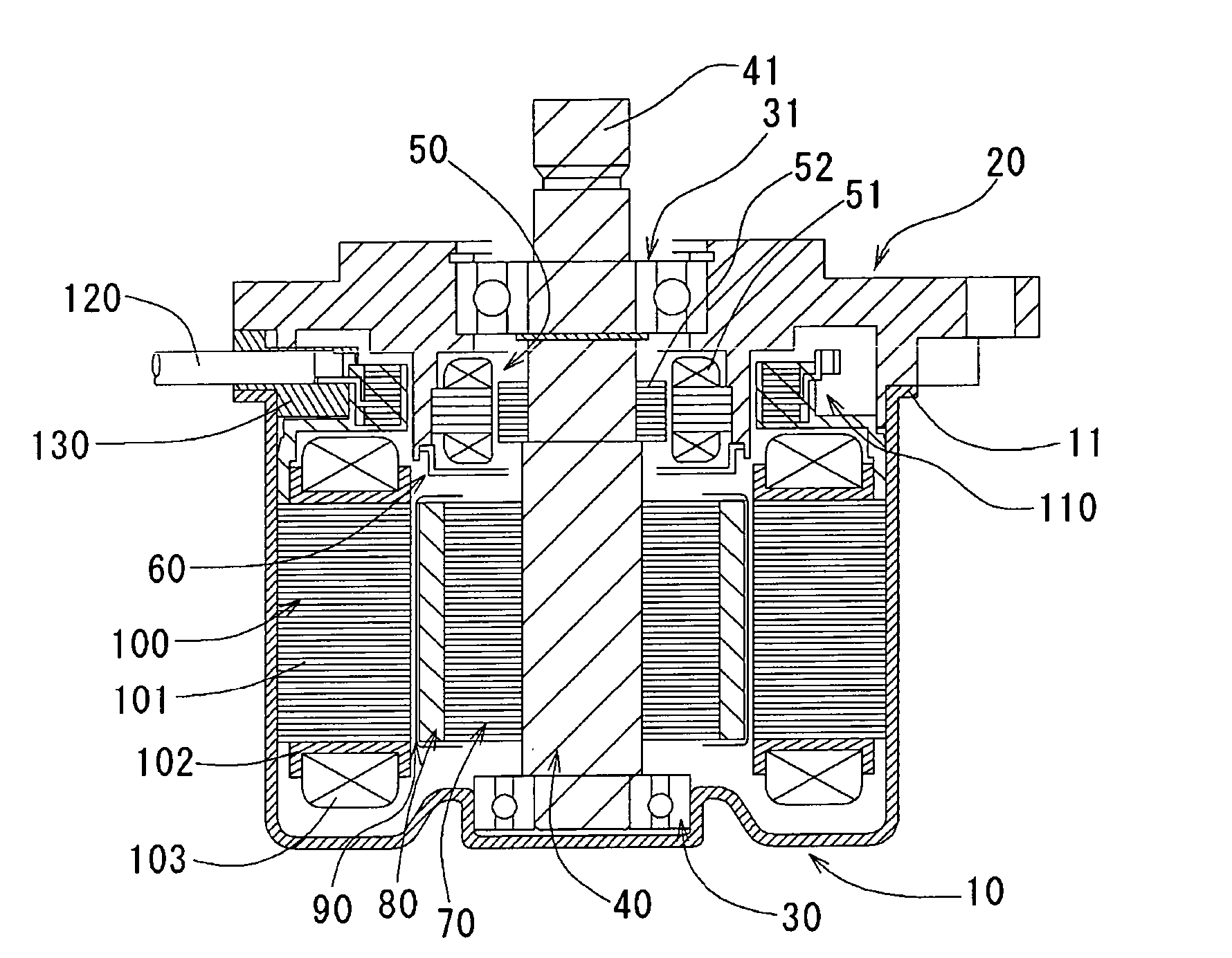
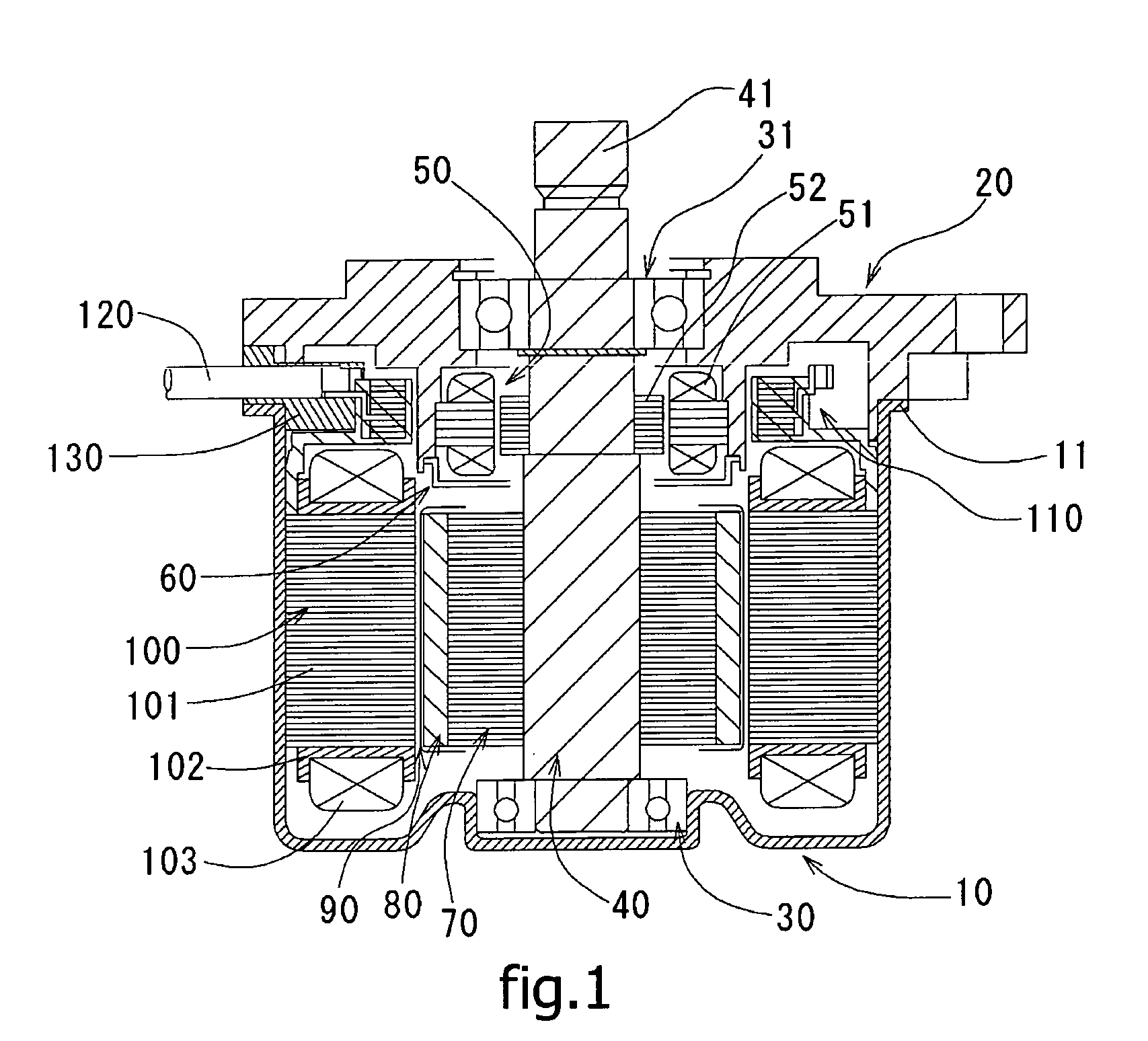
[0024]FIG. 1 is a schematic cross section showing an embodiment of a brushless motor according to the invention.

[0025] Referring to FIG. 1, a housing 10 has an almost cylindrical shape formed by plastic working such as press on a steel sheet or the like and is open axially upward. An end face on the axially upper side of the housing 10, that is, an end face of the opening has an extended part 11 which extends horizontally outward in a radial direction. A bracket 20 obtained by casting an aluminum alloy with a die cast or the like to be formed in an almost hollow cylindrical shape so as to be in contact with the extended part 11 and a part of the cylindrical part on the opening side is fixed.

[0026] Ball bearings 30 and 31 are fixed to a lower end face of the housing 10 and in an upper part of an inner cylindrical part 22 which will be described later of the bracket 20, respectively. A shaft 40 is press fit and fixed to the ball bearings 30 and 31 and is supported rotatably. An uppe...


PUM


Abstract

A second bracket part for holding a resolver stator of a resolver as position detecting means is inserted in an opening hole in a first bracket part. An expanded part formed in the second bracket part and the opening hole in the first bracket hole are connected to each other with a fixing member. A through hole in which the fixing member for the expanded part is inserted has a circular arc shape. By reducing the fixing strength of the fixing member, the second bracket part can be made movable in the circumferential direction.

Description

BACKGROUND OF THE INVENTION [0001] 1. Technical Field [0002] The present invention relates to a brushless motor and, more particularly, to a motor for an electric power steering device which supports steering effort of a steering wheel of a vehicle. [0003] 2. Description of the Related Art [0004] In recent years, electric power steering (EPS) system that supports steering operation by rotating a motor with a vehicle battery is employed. The EPS system is attracting attention as an efficient system with smaller power loss of an engine as compared with the case of generating an oil pressure by rotation of the engine. On a motor used for such an EPS system, a part as position detecting structure is mounted in order to realize high-precision control. [0005] Since the rotary shaft of a motor used for the EPS system is connected to the driver indirectly via a steering wheel, cogging and torque ripple generated from the motor is directly transmitted as an abnormal state of the steering whe...

Claims


Application Information

Patent Timeline
IPC IPC(8): H02K11/00H02K47/00H02K23/66
CPCH02K7/20H02K29/12H02K11/0005H02K11/0141
Inventor NAKANISHI, KEITAKATAOKA, NAKABA
Owner NIPPON DENSAN CORP
Why Eureka
Try Eureka