

Tenon Rod and Tenon Joint
- Summary
- Abstract
- Description
- Claims
- Application Information
AI Technical Summary
Benefits of technology
Problems solved by technology
Method used
Image

Examples
first embodiment
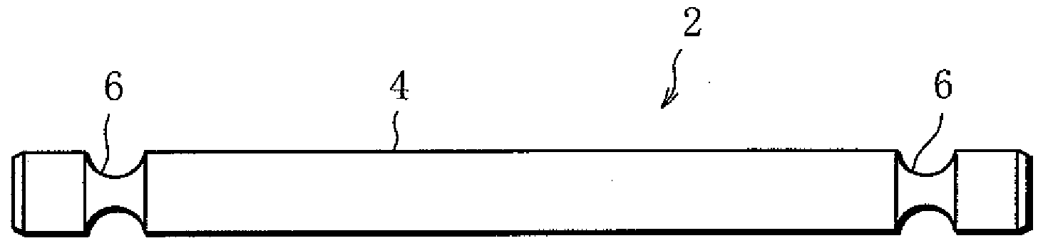
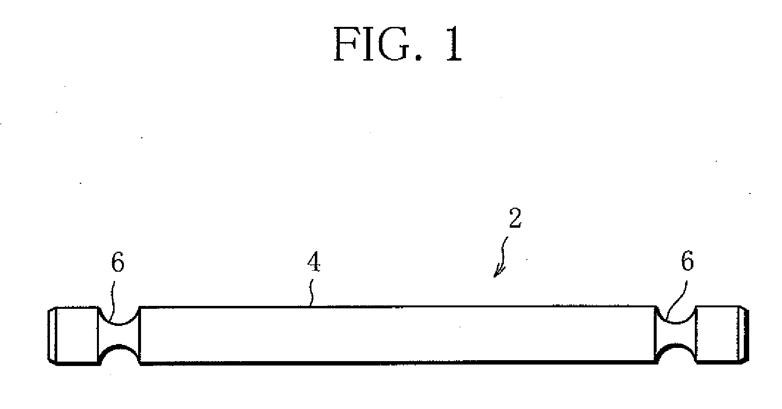
[0044]FIG. 1 shows a tenon rod 2 according to a
[0045]The tenon rod 2 includes a rod body 4 made of a metal round bar. The rod body 4 has an annular, or circumferential groove 6 in each end portion. The annular groove 6 is a circular arc in cross section, and extends all around the rod body 4. The annular groove 6 is intended to engage with the aforementioned pin, so-called drift pin.
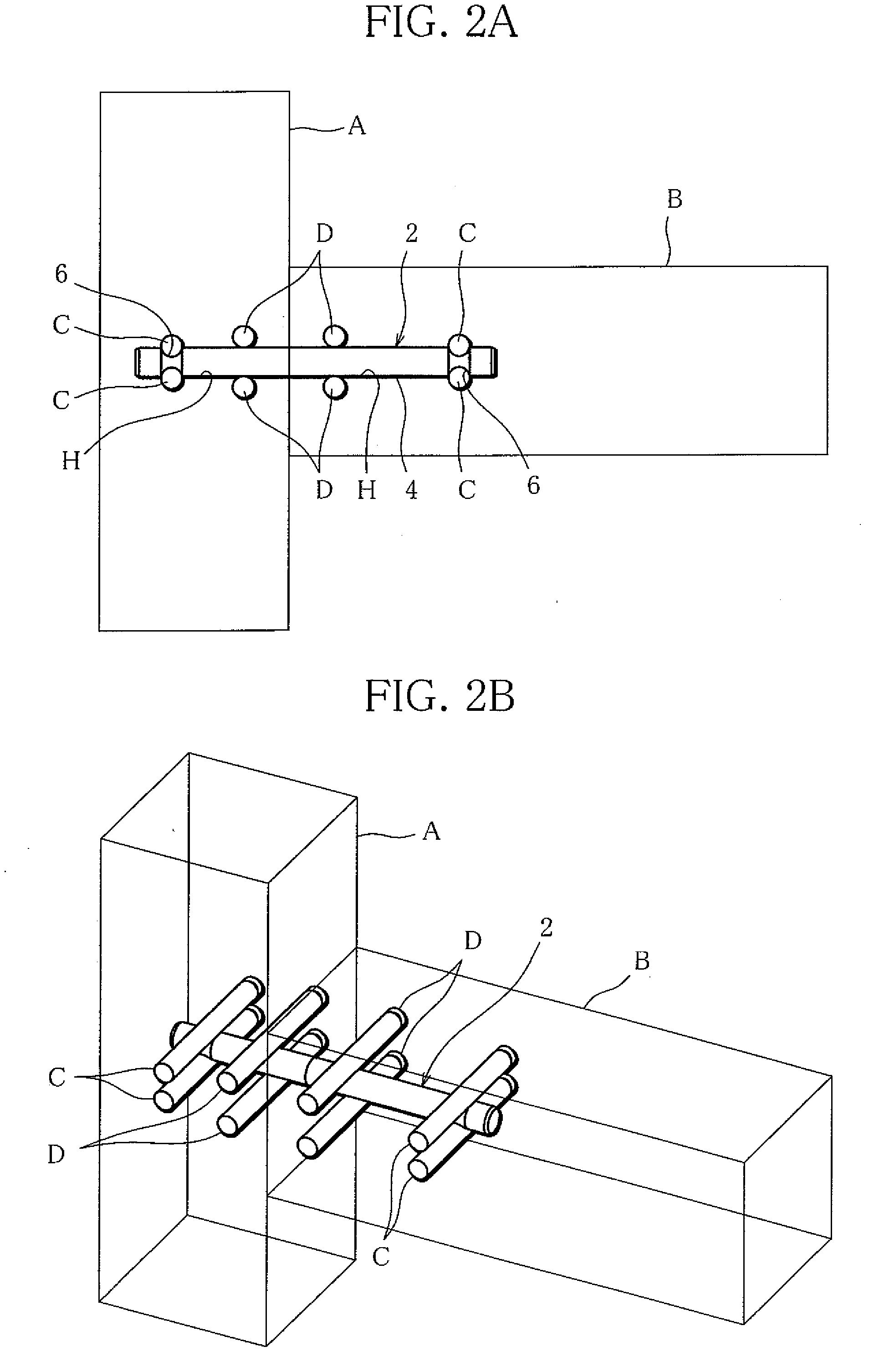
[0046]FIGS. 2A and 2B show how to use the above-described tenon rod 2.
[0047]In FIG. 2, the tenon rod 2 and drift pins are used to join a post A and a beam B. The post A and the beam B are made of wood and each have a horizontally-extending mortise H to receive the tenon rod 2. The mortises H are arranged such that the post A and the beam B is in contact with each other, with their mortises' open ends met together.
[0048]Further, the post A and the beam B each have a plurality of pin insertion holes at specified locations. The pin insertion holes extend horizontally, across the mortise H, in pairs of an up...
second embodiment
[0069]FIG. 12 shows a tenon rod 2 according to a
[0070]In comparison with the tenon rod 2 in FIG. 3, the tenon rod 2 in FIG. 12 differs only in that it has a helical groove 16 in place of the annular groove 6. The helical groove 16 is a circular arc in cross section.
[0071]FIGS. 13A, 13B and 13C show how to use the tenon rod 2 of FIG. 12.
[0072]As seen from FIG. 13, the tenon rod 2 of FIG. 12 is inserted in a mortise H of a beam B, with the hexagonal head 8 projecting from the end face of the beam B. In this state, a pair of drift pins C are fitted in the spiral groove 16 on the upper and lower sides of the tenon rod 2 to hold the tenon rod 2 between them. Due to the helical configuration of the helical groove 16, the drift pins C are at different axial locations with respect to the tenon rod 2. FIG. 13 also shows a drift pin D and a drift pin J. The drift pin D is set in contact with the cylindrical surface of the rod body 4 as mentioned above, while the drift pin J is fitted in the h...
third embodiment
[0100]FIG. 25 shows a tenon rod 2 according to a
[0101]The tenon rod 2 of FIG. 25 has a helical groove 16 in a first end portion of the rod body 4, an annular groove 6 in the opposite, second end portion thereof, and a hexagonal tail 14 at the second end of the rod body 4.
[0102]FIGS. 26A, 26B and 26C show how to use the tenon rod 2 of FIG. 25.
[0103]As seen from FIG. 26, the tenon rod 2 of FIG. 25 is used to join a beam B to a post A.
[0104]FIG. 27 shows a variant of the tenon rod according to the third embodiment.
[0105]The tenon rod 2 of FIG. 27 differs from the tenon rod of FIG. 25 only in that it has a hexagonal hole 15 in place of the hexagonal tail 14.
[0106]FIGS. 28 to 30 show a tenon joint according to an embodiment.
[0107]The tenon joint comprises a tenon rod 30 shown in FIG. 28 and a drift pin 32 shown in FIGS. 29A, 29B and 29C.
[0108]The tenon rod 30 has an annular groove 6 in a first end portion of a rod body 4, and the opposite, second end portion of the rod body is formed int...
PUM
 Abstract
Description
Claims
Application Information