Monopole tower and wind turbine generator having monopole tower

a technology of wind turbine generator and monopole tower, which is applied in the direction of electric generator control, machines/engines, mechanical equipment, etc., can solve the problems of difficult to increase achieve the effect of reducing the cost of the wind turbine generator, maximizing the outside diameter of the tower shell, and improving section efficiency

Active Publication Date: 2011-11-17
MITSUBISHI HEAVY IND LTD
View PDF4 Cites 18 Cited by
  • Summary
  • Abstract
  • Description
  • Claims
  • Application Information

AI Technical Summary

Benefits of technology

[0008]The conventional tower supporting structure has a higher effect by disposing the anchor bolt 10 on the outside of the tower shell 21, so that the base flange often extends toward the outside of the tower shell 21. Further, since the shell member made of steel and having the cylindrical shape is a main strength member, the larger the outside diameter of the tower shell 21 is, the higher a section efficiency is. The monopole tower made of steel is therefore demanded to increase the outside diameter of the shell as much as possible within the range in which the weight can be reduced.

Problems solved by technology

Consequently, it is difficult to increase the outside diameter of the tower shell 21 to the constraint condition.

Method used


Image

  • Monopole tower and wind turbine generator having monopole tower
  • Monopole tower and wind turbine generator having monopole tower
  • Monopole tower and wind turbine generator having monopole tower

Examples


first embodiment

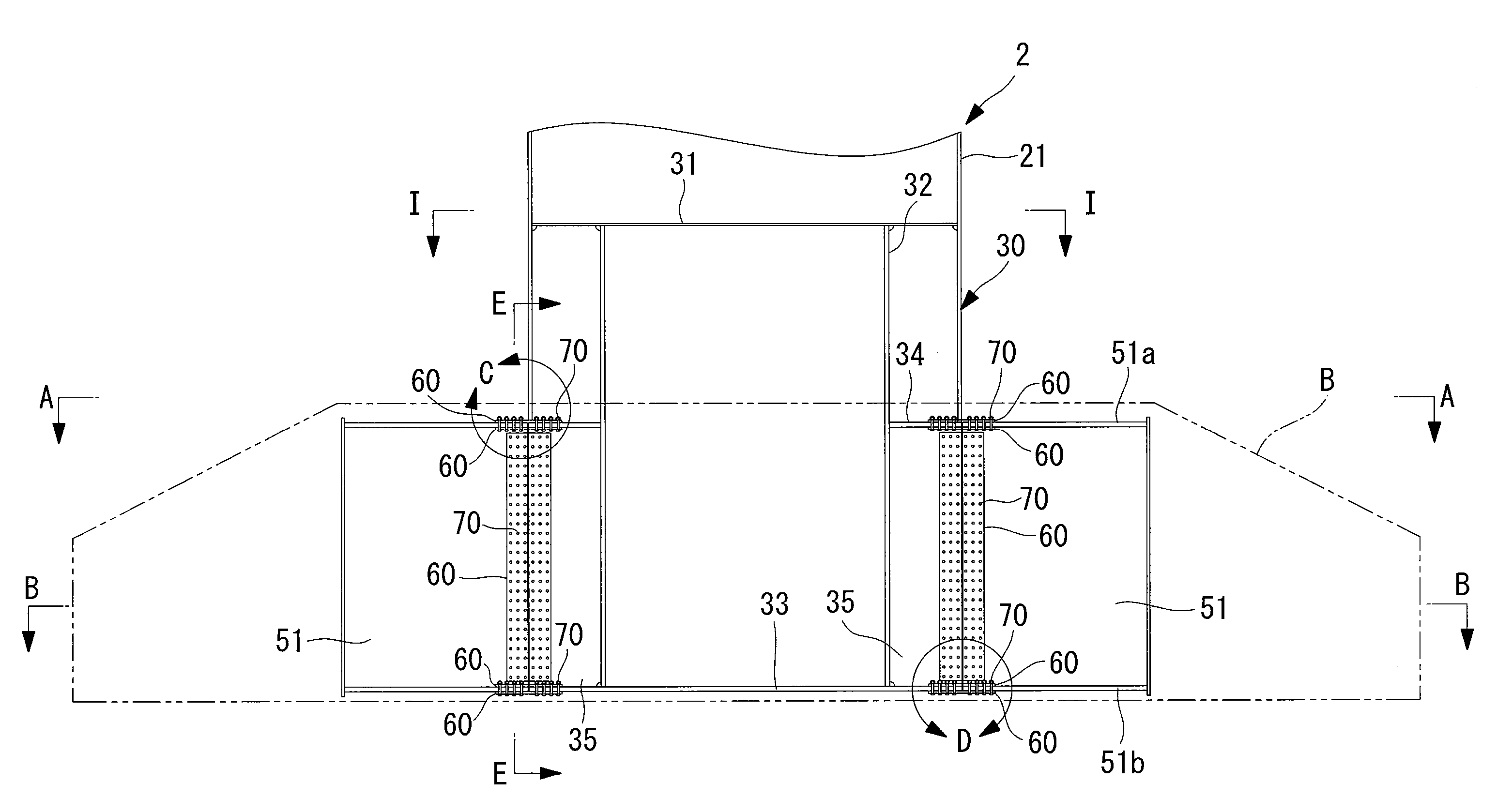
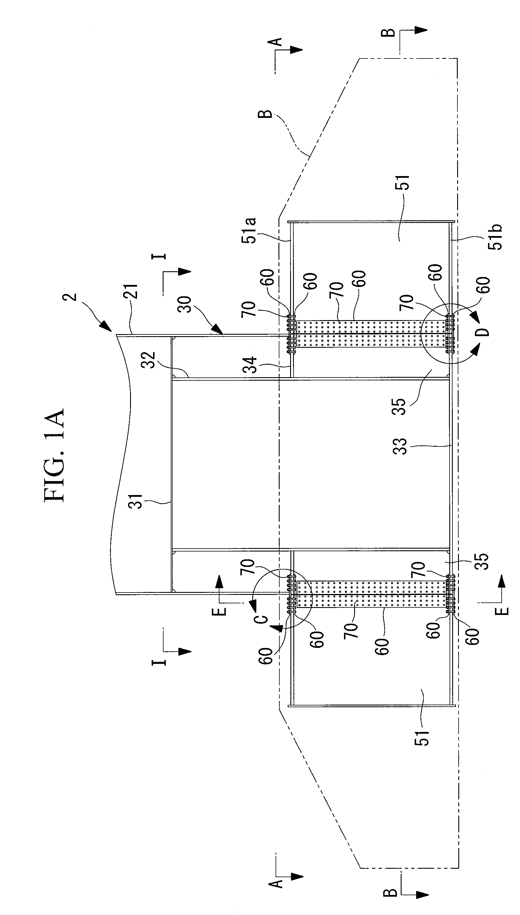
[0072]A tower supporting structure for supporting the tower 2 upright on the foundation B will be described below with reference to FIGS. 1A to 6.

[0073]In the tower supporting structure shown in the diagram, a foundation coupling part 30 is formed on the lower end side of the tower 2. The foundation coupling part 30 is inserted in a tower coupling space 50 which is not yet filled with concrete and is preliminarily formed in the center of the foundation B to support the tower 2 upright.

[0074]In the foundation coupling part 30 inserted in the tower coupling space 50, a coupling member on the side of the foundation coupling part 30 which will be described later and a foundation-side bracket 51 provided as a coupling member in the tower coupling space 50 are coupled to each other via a splice plate 60 and bolts and nuts 70. After that, the space in the tower coupling space 50 is filled with concrete, and the concrete is solidified, thereby completing mounting of the tower 2.

[0075]The ab...

second embodiment

[0099]A second embodiment of the tower supporting structure in which the tower 2 is provided upright on the foundation B will now be described with reference to FIGS. 9 and 10. The same reference numerals are designated to parts similar to those of the foregoing embodiment and their detailed description will not be repeated.

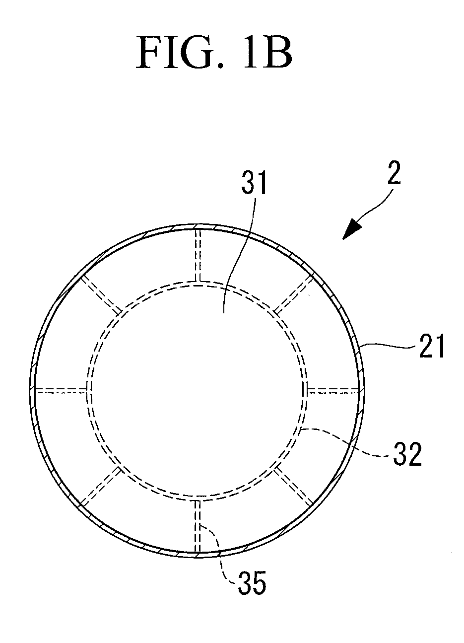
[0100]The second embodiment relates to a foundation coupling part 30B employing an inner cylinder 32A having a circular truncated cone shape whose upper end on the larger diameter side is coupled to the tower shell 21. That is, the inner cylinder 32A of the embodiment has a structure that the upper end having a large diameter is directly welded to the inner wall of the tower shell 21, and the lower end having a small diameter is welded to the bottom plate 33.

[0101]Consequently, stress transfer from the tower shell 21 to the inner cylinder 32A is direct and smooth different from that in the cylinder shape in which stress is transferred via the diaphragm 31. Theref...


PUM


Abstract

The present invention provides a monopole tower having a tower supporting structure in which the outer dimension of a tower shell is the maximum dimension by eliminating a base plate which extends toward the outside of the tower shell. In a monopole tower provided upright on a foundation B, a lower end side of the tower 2 comprised a tower-side coupling member in a range equal to or less than outside diameter of a tower shell 21. In a space comprising a foundation-side coupling member provided on the foundation B, the foundation-side coupling member and the tower-side coupling member are coupled by welding, a bolt using a splice plate, or a rivet.

Description

TECHNICAL FIELD[0001]The present invention relates to a monopole tower and a wind turbine generator having a monopole tower (support).BACKGROUND ART[0002]In a wind turbine generator, a rotor head having wind turbine blades receives wind force and rotates, the rotation is increased by a speed-up gear, and power is generated by a power generator which is driven by the increased rotation.[0003]The rotor head is mounted on a tower for a wind turbine (hereinbelow, called “tower”), attached to an end of a nacelle which can yaw, and supported so as to be rotatable about the rotary axis in an substantially horizontal direction.[0004]Generally, the tower for a wind turbine often employs a monopole type made of steel using a cylindrical shell, and has a structure that a base plate provided at the lower end of the tower shell is fixed to a foundation made of reinforced concrete by an anchor bolt.[0005]FIGS. 11 and 12 show a conventional tower supporting structure. At the lower end of a tower 2...

Claims


Application Information

Patent Timeline
Patent Type & Authority Applications(United States)
IPC IPC(8): F03D11/04E02D27/42E04H12/00
CPCE02D27/42Y02E10/728F05B2240/913F03D11/045F03D13/22E02D27/425Y02E10/72
Inventor MURATA, HAJIME
Owner MITSUBISHI HEAVY IND LTD
Why Eureka
Try Eureka