

Non-aqueous secondary battery and its control method
- Summary
- Abstract
- Description
- Claims
- Application Information
AI Technical Summary
Benefits of technology
Problems solved by technology
Method used
Image

Examples
embodiment 2-1
[0163] (Embodiment 2-1)
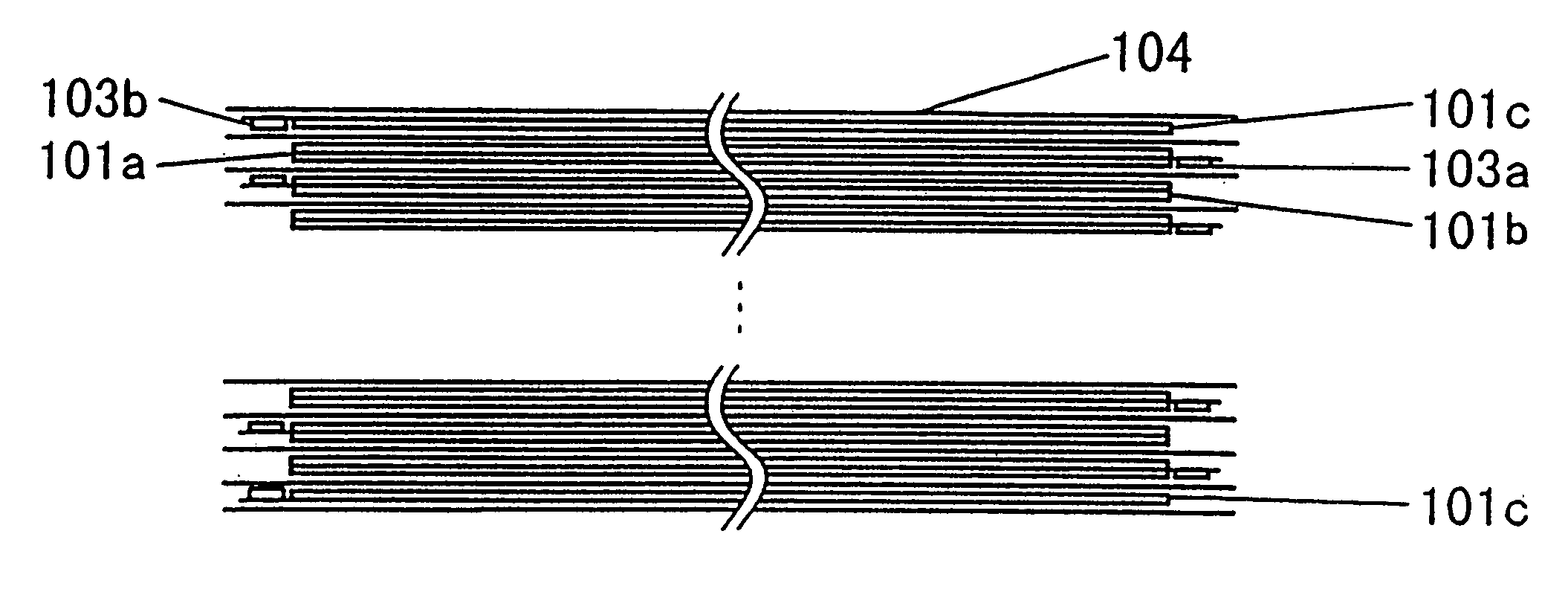
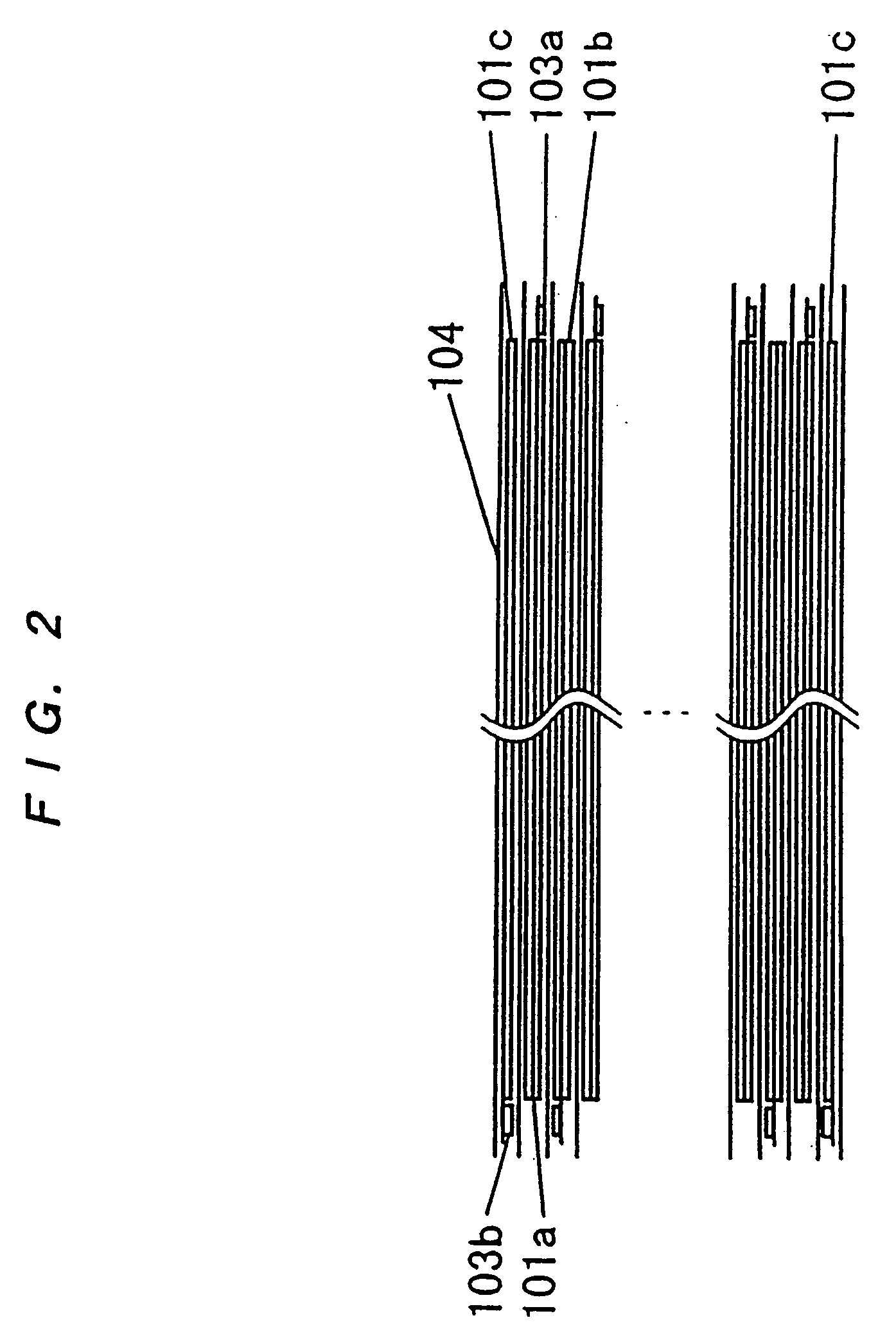
[0164] (1) A positive-electrode mixture slurry was obtained by mixing 100 parts by weight of spinel-type LiMn.sub.2O.sub.4 (made by SEIMI CHEMICAL, product No. M063), 10 parts by weight of acetylene black, and 5 parts by weight of polyvinylidene fluoride (PVdF) with 100 parts by weight of N-methylpyrrolidone (NMP). A positive electrode was obtained by applying the slurry to both sides of aluminum foil having a thickness of 20 mm and serving as a current collector, and by drying and pressing the foil. FIG. 6 is an illustration of an electrode. In the case of this embodiment, the coating area (W1.times.W2) of an electrode 101 was 268.times.178 mm.sup.2 and the slurry was applied to both sides of a current collector 102 of 20 mm thickness at a thickness of 128 mm. As a result, the electrode thickness t was 276 mm. One of the edge portions of the shorter side of the current collector 102 was not coated in 1 cm width and a tab 103 (aluminum with a thickness of 0.1 ...
embodiment 3-1
[0182] (Embodiment 3-1)
[0183] (1) A positive-electrode mixture slurry was obtained by mixing 100 parts by weight of spinel-type LiMn.sub.2O.sub.4 (made by SEIMI CHEMICAL; product No. M063), 10 parts by weight of acetylene black, and 5 parts by weight of polyvinylidene fluoride (PVdF) with 100 parts by weight of N-methylpyrrolidone (NMP). A positive electrode was obtained by applying the slurry to both sides of an aluminum foil having a thickness of 20 mm serving as a current collector, and drying and pressing the foil. FIG. 6 is an illustration of the electrode. In the case of this embodiment, the coating area (W1.times.W2) of the electrode 101 was 268.times.178 mm.sup.2 and slurry was applied to both sides of the current collector 102 of 20 mm thickness at a thickness of 128 mm. As a result, the electrode thickness t was 276 mm. One of the edge portions of the shorter side of the current collector 102 was not coated in 1 cm width and a tab 103 (aluminum with a thickness of 0.1 mm a...
embodiment 3-2
[0191] (Embodiment 3-2)
[0192] A positive electrode was formed which was the same as that of the embodiment 3-1 except that slurry was applied to both sides of a current collector 102 at a thickness of 130 mm and the electrode thickness t was 280 mm.
[0193] Then, a negative electrode was used which was the same as the above negative 4 except for the coating thickness of the electrode. The coating area (W1.times.W2) of an electrode 101 is 270.times.180 mm.sup.2 and slurry is applied to both sides of the current collector 102 of 14 mm at a thickness of 70 mm. As a result, the electrode thickness t is 154 mm. T slurry was applied to only one side by the same method and a single-sided electrode having a thickness of 84 mm was formed in accordance with the same method except for the single-sided application of the slurry. Other points were the same as those of the embodiment 3-1.
[0194] As a result of forming a battery by the same method as the case of the embodiment 3-1 and measuring the c...
PUM
 Abstract
Description
Claims
Application Information