Power tool

a power tool and tool body technology, applied in the field of power tools, can solve the problem of relatively long time required for screw tightening, and achieve the effect of increasing the output torque of the blushless motor

Inactive Publication Date: 2006-03-07
MAKITA CORP
View PDF26 Cites 78 Cited by
  • Summary
  • Abstract
  • Description
  • Claims
  • Application Information

AI Technical Summary

Benefits of technology

[0006]It is, accordingly, an object of the present teachings to provide a technique to increase efficiency of the output torque of the blushless motor to drive a power tool.
[0007]According to the present teachings, a representative power tool may comprise a tool bit, a brushless motor to drive the tool bit, a battery to operate the brushless motor and a control device. The control device may operate the brushless motor by means of the battery. The control device may include an advance angle controlling section to control an advance angle of the brushless motor. According to the present teachings, the advance angle of the brushless motor may be determined based upon indexes that reflect working condition of the tool bit when the brushless motor is under the operation. By reflecting the working condition of the tool bit to the determination of the advance angle of the brushless motor, the brushless motor can be operated with higher efficiency under the various working condition such as a hard joint operation and a soft joint operation.

Problems solved by technology

On the other hand, when the soft joint operation is selected, time required for tightening the screw takes relatively long, and therefore, it is required to achieve stable tightening operation solely by means of the output torque of the motor without utilizing the inertia force of the rotor.

Method used


Image

  • Power tool
  • Power tool
  • Power tool

Examples


Embodiment Construction

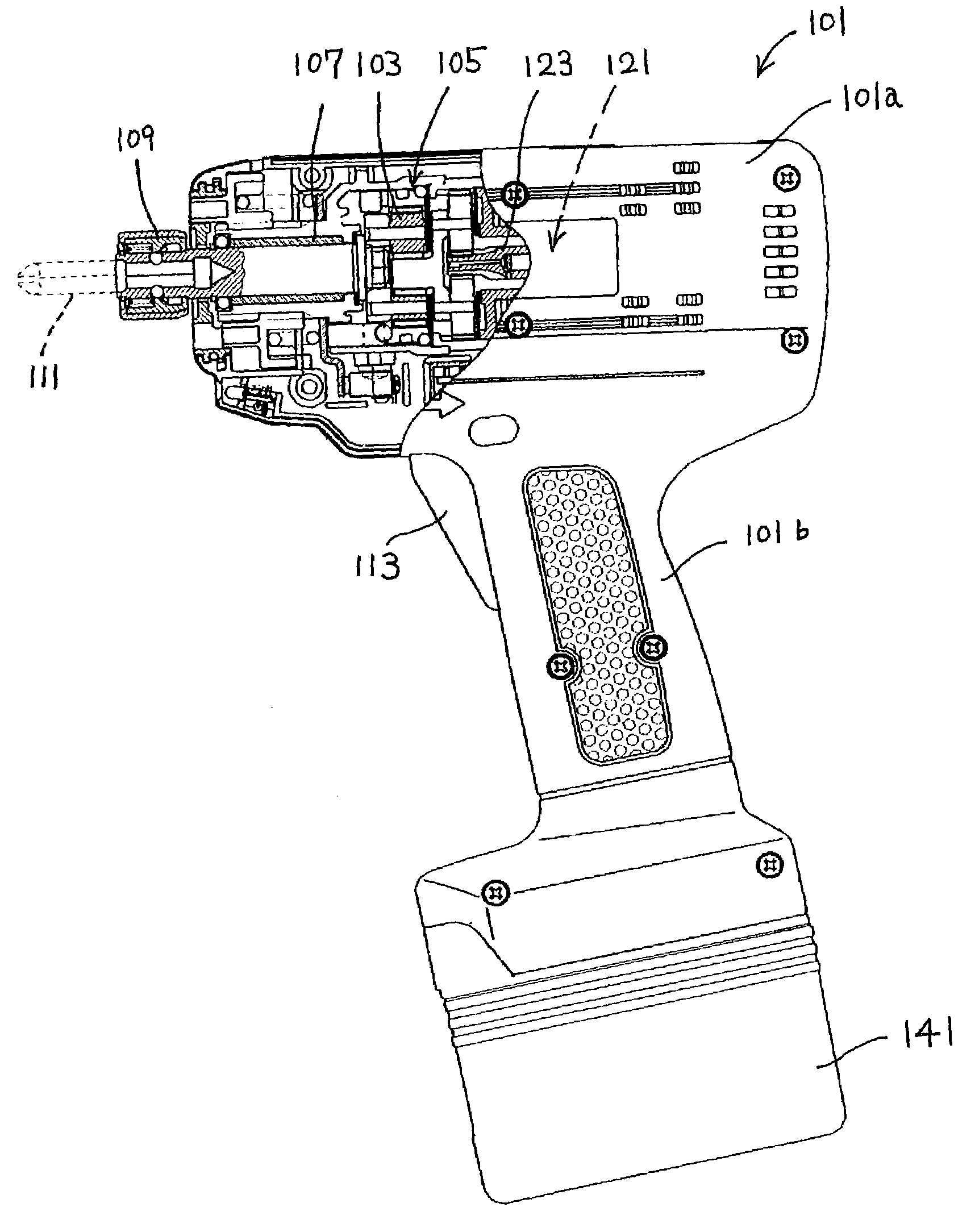
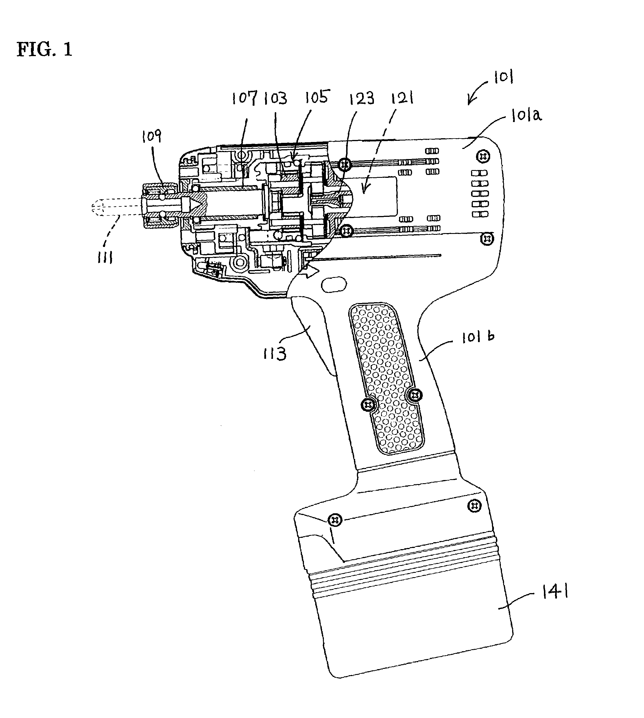
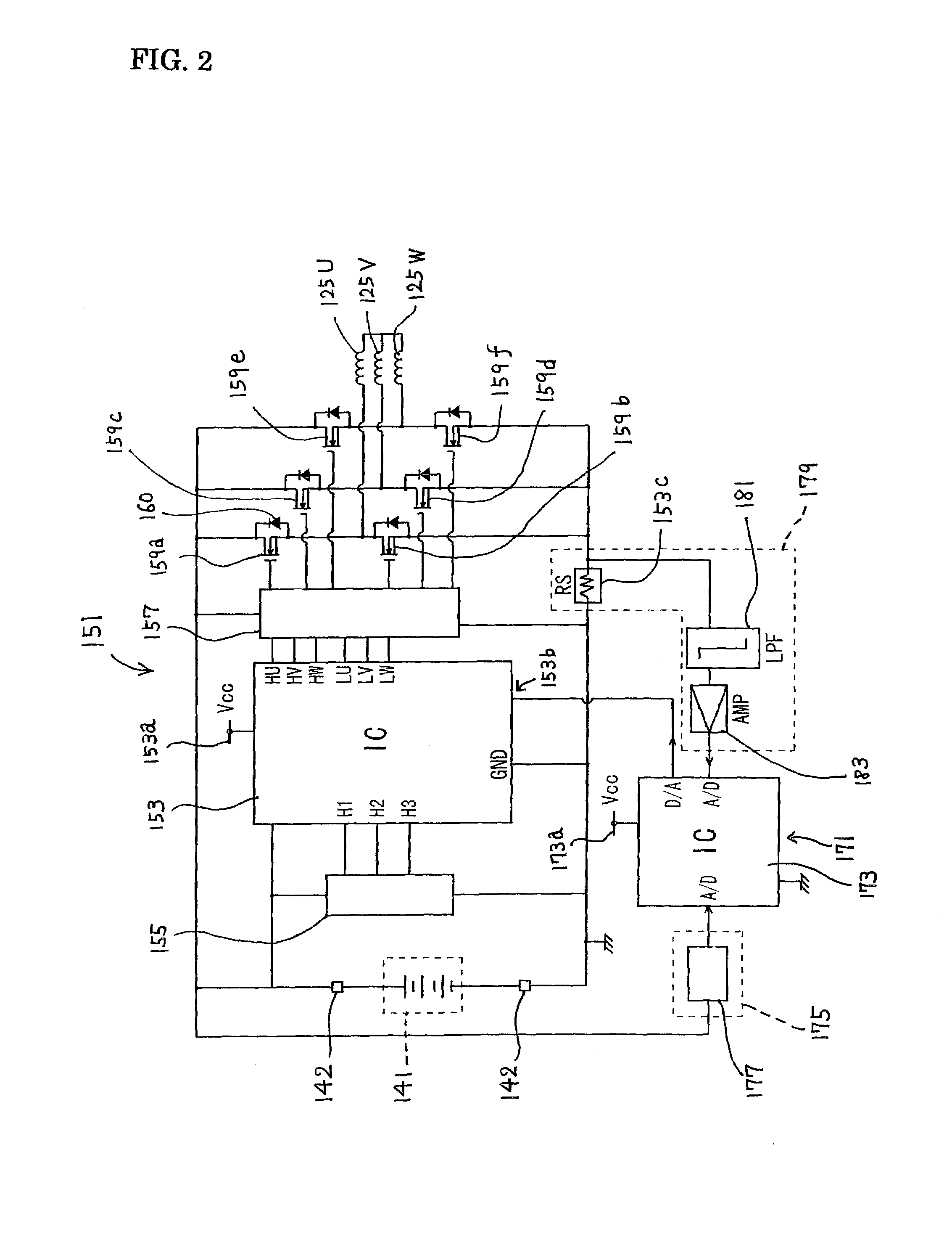
[0018]In accordance with the present teachings, representative power tool may include a tool bit, a brushless motor, a battery and a control device. The brushless motor may have a rotor. The brushless motor may drive the tool bit by rotation of the rotor. The battery may be detachably coupled to the power tool. The battery may provide direct current to the brushless motor. The control device may operate the brushless motor by means of the battery. Further, the control device may include an advance angle controlling section to control an advance angle of the brushless motor based upon indexes that reflect working condition of the tool bit when the brushless motor is under the operation.

[0019]As for the tool bit, any type of bits that can be mounted to the power tool may be embraced. For example, tool bit for drills, saws, grinders, impact drivers, impact wrenches, cutters, trimmers, circular saws, and reciprocating saws. Particularly, the present teachings may be preferably applied t...


PUM


Abstract

It is an object of the present invention to provide a technique to increase efficiency of the output torque of the blushless motor to drive a power tool. A representative power tool may comprise a tool bit, a brushless motor to drive the tool bit, a battery to operate the brushless motor and a control device. The control device may operate the brushless motor by means of the battery. The control device may include an advance angle controlling section to control an advance angle of the brushless motor. According to the present teachings, the advance angle of the brushless motor may be determined based upon indexes that reflect working condition of the tool bit when the brushless motor is under the operation. By reflecting the working condition of the tool bit to the determination of the advance angle of the brushless motor, the brushless motor can be operated with higher efficiency under the various working condition such as a hard joint operation and a soft joint operation.

Description

BACKGROUND OF THE INVENTION[0001]1. Field of the Invention[0002]The present invention relates to a power tool driven by a brushless motor and, more particularly, to a technique that can maximize the output efficiency of the brushless motor in relation to the operation of the power tool.[0003]2. Description of the Related Art[0004]In tightening screws by utilizing a screwdriver, two types of operations as shown in FIGS. 8 and 9 are known. The operation type as shown in FIG. 8 is referred to as “hard joint” operation. To the contrary, the operation type as shown in FIG. 9 is referred to as “soft joint” operation. During the hard joint operation, the tool bit only rotates by a relatively small angle until the tightening operation is completed after the tool bit has contacted the work-piece. On the other hand, during the soft joint operation, tool bit rotates by a relatively large angle (the tool bit turns twice or more) until the tightening operation is completed.[0005]The rotational a...

Claims


Application Information

Patent Timeline
Patent Type & Authority Patents(United States)
IPC IPC(8): E21B4/04B25F5/00B25B21/00B25B23/147H02P6/06H02P6/08H02P6/14H02P6/15H02P6/28
CPCB25B23/147B25B21/00
Inventor YAMAMOTO, HIROKATSU
Owner MAKITA CORP
Why Eureka
Try Eureka