Power supply cord winding reel device of vacuum cleaner

A technology for vacuum cleaners and power cords, which is applied to the installation of cables, the arrangement of cables between relatively moving parts, electrical components, etc., which can solve the problem of large spring restoring elasticity, unfavorable power cords 84 continuing to wrap, and unfavorable power cords 84 being pulled out. and other problems to achieve the effect of avoiding failures

Inactive Publication Date: 2003-07-02
LG ELECTRONICS (TIANJIN) APPLIANCES CO LTD
View PDF0 Cites 2 Cited by
  • Summary
  • Abstract
  • Description
  • Claims
  • Application Information

AI Technical Summary

Problems solved by technology

[0005] The defect of the above-mentioned power cord reel device is: since the restoring elastic force of the spring arranged inside the wheel part 80 is a variable force, in the process of winding the power cord 84 on the wheel part 80, the restoring elastic force of the spring is very large at the beginning, then gradually decrease
Therefore, when initially starting to wind the power cord 84, under the action of the restoring force of the spring, the wheel member 80 rotates at a high speed, and it is easy to cause many turns of the power cord 84 to be wound on the wheel member 80 in an instant, resulting in being wound. The power cords 84 are crossed and stacked together, which is not conducive to the continued winding of the power cords 84, and is also not conducive to pulling the power cords 84 out in the future.
This situation is exacerbated when winding very long power cords 84

Method used


Image

  • Power supply cord winding reel device of vacuum cleaner
  • Power supply cord winding reel device of vacuum cleaner
  • Power supply cord winding reel device of vacuum cleaner

Examples


Embodiment Construction

[0018] The power cord reel device for vacuum cleaners of the present invention will be further described in detail in conjunction with the accompanying drawings and specific embodiments:

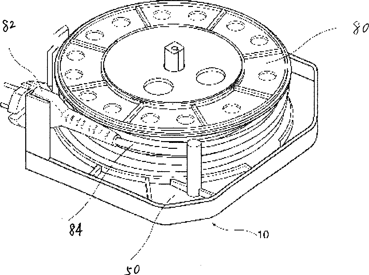
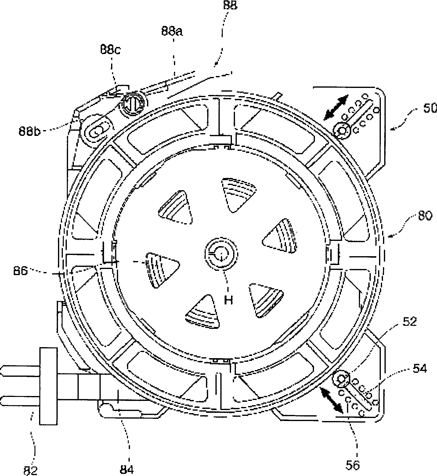
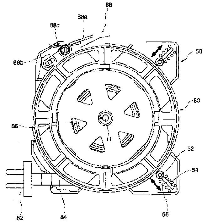
[0019] Such as figure 2 As shown, the power cord reel device for a vacuum cleaner of the present invention includes: a bottom frame 50, a wheel member 80, a braking device 88 and a power cord guide wheel device. The bottom frame 50 is arranged inside the body of the vacuum cleaner; the wheel part 80 is installed on the bottom frame 50, and the support shaft H on the bottom frame 50 is its rotation axis, and the power cord 84 can be wound on the wheel part 80; the braking device 88 Set on one side of the underframe 50, the braking device 88 includes: a release lever 88a, a brake drum 88b and a brake spring 88c; the brake drum 88b is arranged at the end of the release lever 88a, and the brake spring 88c is a The torsion spring elastically supports the brake drum 88b; the power cord guide whe...


PUM


Abstract

A power cord winder for vacuum cleaner is composed of a base, a reel, a brake unit and a guide wheel unit of power cord. The brake unit consists of control lever, braking drum and braking spring. The guide wheel unit comprises guide wheel with slot and spring. It features that the power cord is orderly wound on the reel turn by turn close to each other.

Description

technical field [0001] The invention relates to a vacuum cleaner, in particular to a power cord reel device for a vacuum cleaner. Background technique [0002] The body of the ordinary vacuum cleaner is generally provided with a pump for generating suction, a power cord for applying power to the pump, and a power cord reel device for storing the power cord. [0003] Such as figure 1 As shown, a plug 82 is provided at the front end of the above-mentioned power cord 84 . The above-mentioned power cord reel device 10 is built in the body of the vacuum cleaner, and its structure includes: a bottom frame 14 and a rotatable wheel part 80 . Typically a power cord 84 is wound around the wheel member 80 . A spring (not shown) is built in the inside of the wheel member 80, and a wheel member braking device (not shown) is provided to stop the rotation of the wheel member 80 by the elastic force of the spring. When the braking device of the wheel part is not in operation, the wheel ...

Claims


Application Information

Patent Timeline
Patent Type & Authority Applications(China)
IPC IPC(8): A47L9/26
Inventor 朴俊相
Owner LG ELECTRONICS (TIANJIN) APPLIANCES CO LTD
Why Eureka
Try Eureka