Movable light-guide fiber display

A technology of optical fiber and display, which is applied in the direction of instruments, identification devices, etc., can solve the problems of dazzling brightness, irregular radiation, easy to produce deviation, etc., and achieve the effect of avoiding uneven brightness and enhancing stability

Inactive Publication Date: 2021-01-29
广州优易机械科技有限公司
View PDF0 Cites 2 Cited by
  • Summary
  • Abstract
  • Description
  • Claims
  • Application Information

AI Technical Summary

Problems solved by technology

[0002] Store the electric energy of the solar cell in the accumulator, use the electric power to make the LED emit light, use the optical fiber to guide the light to the display panel, and draw characters and graphics in the form of a dot matrix on the front surface of the optical fiber. In order to improve the visual roundness between the graphics, the blank area between the light source points is small, because the size of the light source point structure is not easy to expand and shrink, resulting in too dense light source points of the same size, resulting in light diffraction phenomenon, resulting in pattern distortion It is not clear, so that the visual effect at the edge of the pattern is poor, and the irradiation direction of the light in the process of dot diffusion is in a scattering state. Due to the intersection phenomenon of light spot expansion during irradiation, the radiation is irregular, and deviations are likely to occur, resulting in Phenomenon that the brightness is too dazzling and too dark

Method used


Image

  • Movable light-guide fiber display
  • Movable light-guide fiber display
  • Movable light-guide fiber display

Examples


Embodiment 1

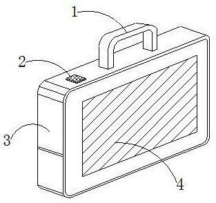
[0023] Such as Figure 1-Figure 5 Shown:

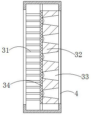
[0024] The present invention is a movable optical fiber display, its structure includes a handle 1, a control switch 2, a mobile box 3, and a display screen 4, the handle 1 is embedded in the upper end of the mobile box 3, and the control switch 2 is installed on the The upper end of the mobile box 3, the display screen 4 is embedded in the side of the mobile box 3, the mobile box 3 is provided with a light source plate 31, a fixed plate 32, a scaling mechanism 33, and a transparent plate 34, and the light source plate 31 is embedded in a transparent The left side of the plate 34, the fixed plate 32 is installed on the right side of the transparent plate 34, the zoom mechanism 33 is located on the right side of the transparent plate 34, the zoom mechanism 33 is located inside the display screen 4, and the zoom mechanism 33 is enlarged. , and at the same time, the fixed plate 32 is a solid body, providing a stress point for the scalin...

Embodiment 2

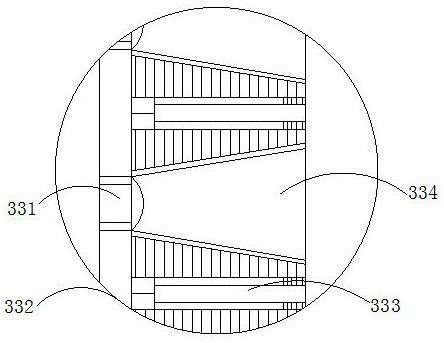
[0031] Such as Figure 6-Figure 7 Shown:

[0032] Wherein, the scattering mechanism 331 is provided with a blocking plate w1, an optical wire w2, a telescopic spring rod w3, a dispersion structure w4, and a bending mirror w5, the bending mirror w5 is embedded and fixed on the right side of the optical wire w2, and the dispersion structure w4 is installed On the right side of the curved mirror w5, the blocking plate w1 is located on the left side of the light wire w2, the telescopic spring rod w3 is installed on the outside of the curved mirror w5, the telescopic spring rod w3 is embedded in the connecting plate 332, and the dispersed structure There is a certain distance between w4 and the curved mirror w5, and an electronic controller is provided on the left side of the telescopic spring rod w3 to control the expansion and contraction of the telescopic spring rod w3, and adjust the distance between the dispersed structure w4 and the curved mirror w5, thereby controlling the c...


PUM


Abstract

The invention discloses a movable light-guide fiber display which structurally comprises a handle, a control switch, a movable box and a display screen. The movable box is provided with a light sourceplate, a fixed plate, a scaling mechanism and a transparent plate. A pressure block in a blocking mechanism is scaled through a controller in a telescopic device, when a telescopic mechanism is retracted, a bent rod is stressed and bent inwards to block light, so that the irradiation range in an irradiation hole is prevented from being too dense, the intensity of the light is adjusted, the diffraction phenomenon caused by too dense irradiation is avoided, and the visual effect at the edge of the pattern is prevented from being influenced by light cross; and the refractivity of a light sourceemitted by a bent mirror is controlled, so that light rays are in a good uniform scattering state, the light rays are prevented from forming a cross phenomenon, the light rays enter a reverse transparent mirror in a scattering structure and are refracted and diffused from rhombic holes after being focused, the light rays reach a uniform state, light sources are scattered orderly, and the problem of non-uniform brightness caused by scattering deviation is solved.

Description

technical field [0001] The invention relates to the field of optical fiber equipment, in particular to a movable optical fiber display. Background technique [0002] Store the electric energy of the solar cell in the accumulator, use the electric power to make the LED emit light, use the optical fiber to guide the light to the display panel, and draw characters and graphics in the form of a dot matrix on the front surface of the optical fiber. In order to improve the visual roundness between the graphics, the blank area between the light source points is small, because the size of the light source point structure is not easy to expand and shrink, resulting in too dense light source points of the same size, resulting in light diffraction phenomenon, resulting in pattern distortion It is not clear, so that the visual effect at the edge of the pattern is poor, and the irradiation direction of the light in the process of dot diffusion is in a scattering state. Due to the interse...

Claims


Application Information

Patent Timeline
Patent Type & Authority Applications(China)
IPC IPC(8): G09F9/305
CPCG09F9/305
Inventor 钟小英
Owner 广州优易机械科技有限公司
Why Eureka
Try Eureka