Fastener of zipper

A zipper button and zipper technology, applied in the field of zipper button, can solve the problems such as the decline of production efficiency of zipper button 101

Inactive Publication Date: 2003-08-27
YKK CORP
View PDF1 Cites 7 Cited by
  • Summary
  • Abstract
  • Description
  • Claims
  • Application Information

AI Technical Summary

Problems solved by technology

Like this, there will be a problem that the p...

Method used


Image

  • Fastener of zipper
  • Fastener of zipper
  • Fastener of zipper

Examples


Embodiment Construction

[0031] Embodiments of the zipper buckle on the zipper according to the present invention will be described in detail below with reference to the accompanying drawings.

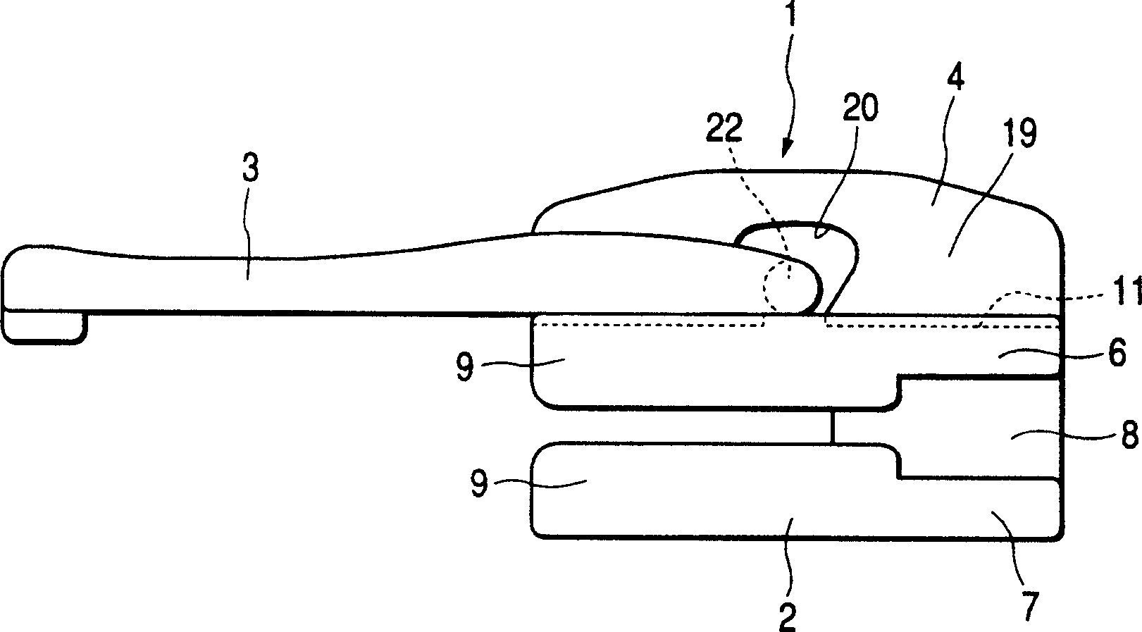
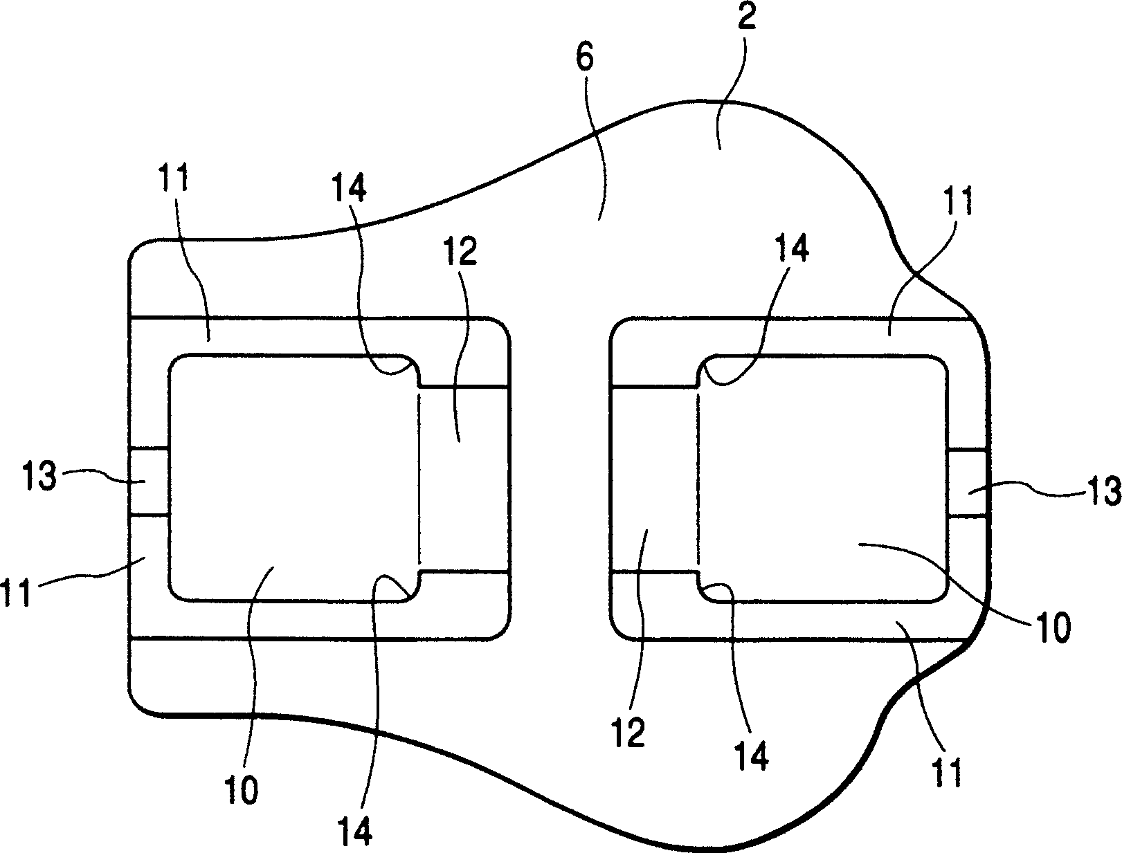
[0032] The zipper buckle on the zipper of the present invention is made up of three parts, as Figures 1 to 6 As shown, it includes a zipper body 2, a handle 3, and a cover 4 for connecting the handle. Wherein, at least the zipper body 2 and the cover 4 connected to the handle are injection molded by thermoplastic resin such as polybutylene terephthalate, polyamide, polyacetal resin or polypropylene. The handle 3 is installed on the formed zipper body 2 through a pivot support mechanism, the cover 4 is arranged thereon and welded with the upper surface of the zipper body 2, thus a zipper body 1 is produced.

[0033] The zipper body 2 of the zipper buckle 1 is connected to the upper blade 6 and the lower blade 7 through a guide column 8, and each edge of the upper blade 6 and the lower blade 7 has a flange 9 f...


PUM


Abstract

A slider (1) for a slide fastener is constituted by three members including a body (2), a pull tab (3) and a cover (4) for pull tab attachment, a concave fitting groove (11) capable of accommodating the lower end face of the cover (11) is provided on the upper surface of the body (2), a welding projection (25) to be protruded outward is provided in a part of the surface of the lower end face (21) of the cover (4) or a part of the bottom face of the fitting groove (11), and the welding projection (25) is welded integrally by ultrasonic processing in a state in which the body (2) formed of a resin and the cover (4) are caused to come in contact with each other by pressure such that a fused resin does not overflow from the fitting groove (11) to an external surface, resulting in the fabrication of a slider which can prevent a fused and solidified lump from being formed and can make a good appearance.

Description

technical field [0001] The present invention relates to a zipper clasp on a zipper, in particular to a connection mechanism between a zipper clasp body and a cover for connecting a handle used in a zipper clasp, the zipper clasp having an automatic or semi-automatic stop device, in which the stop device In the method, an auxiliary column is arranged on the upper surface of the zipper body and the free zipper. Background technique [0002] Usually, the zipper buckle on the traditional zipper includes: a zipper buckle with an automatic stop device, which has an accessory column on the upper surface of the zipper body covered by a cover for attaching a handle; and a free zipper buckle, whose The cover for the additional handle is fastened directly to the upper surface of the zip body. Such as Figure 14 Shown is a zipper fastener 101 disclosed in JP-A-51-12243, wherein the fitting groove 111 is provided on the upper surface of the zipper fastene...

Claims


Application Information

Patent Timeline
IPC IPC(8): A44B19/26B29C65/08
CPCB29C66/30223B29C66/47B29L2005/00B29C66/30221A44B19/26B29C65/08Y10T24/2561Y10T24/2588A44B19/40
Inventor 天神司
Owner YKK CORP
Why Eureka
Try Eureka