
Seat backrest frame structure of vehicle and seat backrest

A technology for seats and vehicles, applied in vehicle seats, seat frames, special positions of vehicles, etc., can solve problems such as unbearable strength

Inactive Publication Date: 2003-09-03
DELTA KOGYO CO LTD
View PDF0 Cites 17 Cited by
  • Summary
  • Abstract
  • Description
  • Claims
  • Application Information

AI Technical Summary

Problems solved by technology

[0005] However, for the conventional rear seats, since the structure of the seat back frame is provided with a frame along the periphery of the flat frame, when the test is carried out according to the above-mentioned automobile specifications, once a large amount of load acts on the seat In the central part of the back, the flat frame will have a protrusion protruding forward, so there is a lack of strength that cannot withstand a large amount of load.

Method used


Image

  • Seat backrest frame structure of vehicle and seat backrest
  • Seat backrest frame structure of vehicle and seat backrest
  • Seat backrest frame structure of vehicle and seat backrest

Examples


no. 1 Embodiment

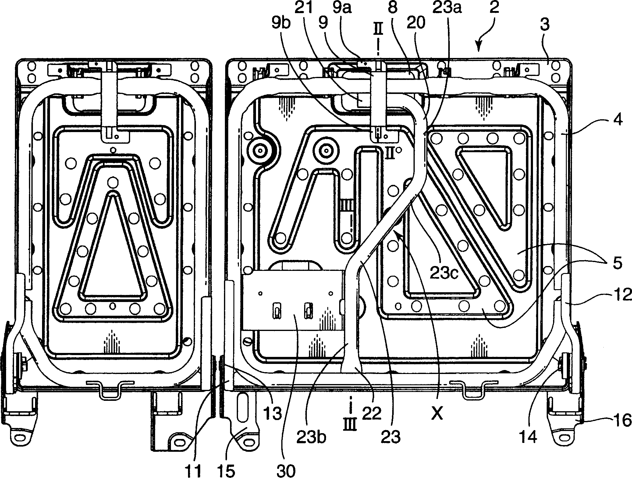
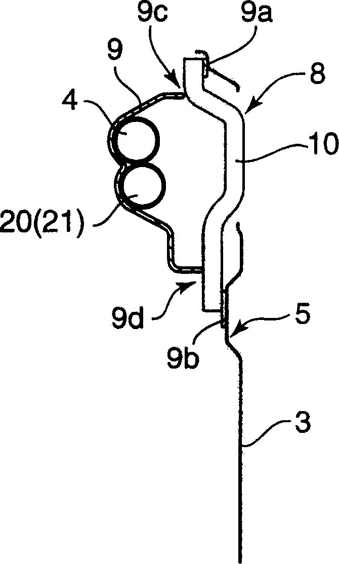
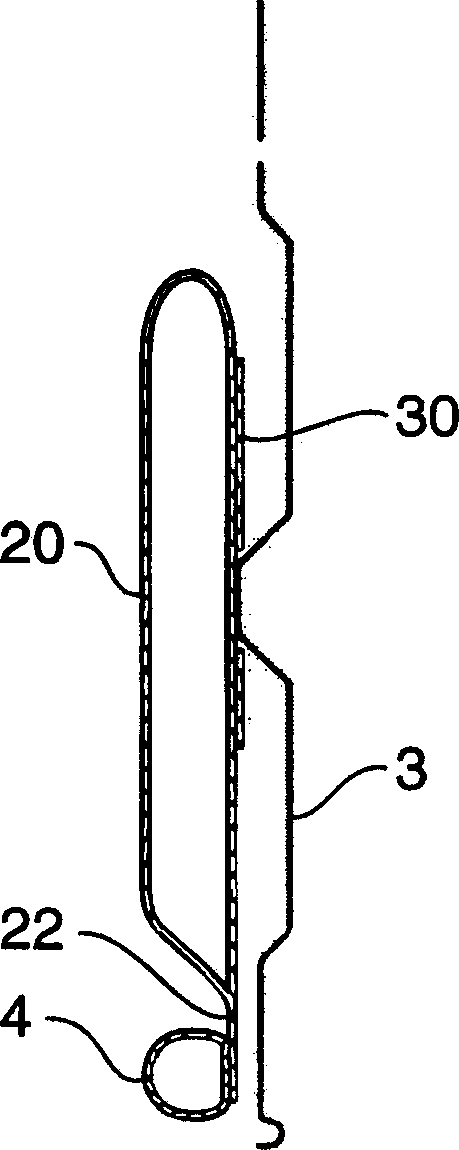
[0024] figure 1 It is a front view showing the structure of a seat back frame for a vehicle in which the present invention is applied to a rear seat divided into two parts of a car. Among them, the seat back with a large area on the right side of the figure is the structure of the vehicle seat back frame according to the first embodiment of the present invention. figure 2 is along figure 1 The sectional view of line II-II, image 3 is along figure 1 Sectional view of line III-III.

[0025] The vehicle seat back frame of the first embodiment includes a seat back bracket 2 and a reinforcing pipe frame 20 as a reinforcing bracket, wherein the seat back bracket has a flat frame 3 and a frame 4, and the two ends of the reinforcing bracket are connected on the upper and lower sides of the frame 4.

[0026] The pallet 3 is made of metal plates such as substantially rectangular steel, and can be partially formed with protrusions 5 protruding to the front side according to a d...

no. 2 Embodiment

[0034] Figure 4 It is a front view showing the structure of the seat back frame for vehicles in which the present invention is applied to the two-part rear seat of a van. The seat back with a large area on the right side of the figure is related to the second embodiment of the present invention. The seat back of the structure of the vehicle seat back frame. Figure 5 is along Figure 4 A cross-sectional view of the V-V line, Image 6 is along Figure 4 Sectional view of line VI-VI. And, with Figure 1~Figure 3 The same reference numerals are attached to the same parts.

[0035] The structure of this vehicle seat back frame is used in the rear seat of a van, and its upper right part is detachably attached to the vehicle body. Although the illustration of the upper right portion of the seat back and the mounting part of the vehicle body is omitted, the structure includes a striker provided on the vehicle body side, and a catch member provided on the seat back bracket 2 si...


PUM


Abstract

A seat back in a vehicle rear seat provided before a trunk includes a seat back frame structure in which a peripheral frame member is arranged along the periphery of a substantially rectangular panel frame member, and a reinforcing pipe frame member having opposite ends thereof coupled to an upper part and a lower part of the peripheral frame member and having an intermediate part formed to pass an external-force receiving portion of the panel frame member where an external force resulting from a possible movement of a luggage placed in the trunk is received. There can be provided a frame structure for the vehicle seat back having an improved strength against an external force exerted resulting from the movement of the luggage placed in the trunk.

Description

technical field [0001] The present invention relates to a structure of a seat back frame provided on a rear seat of a vehicle in front of a trunk of a car and a seat back having the frame structure. Background technique [0002] A seat arranged on a rear seat of a vehicle in front of a trunk of a car generally includes a seat cushion whose lower part is fixed on the floor of the vehicle compartment, and a seat back whose lower part is supported by the rear portion of the seat cushion. As the seat back, there are a seat back that can be tilted forward and a seat back that is fixed to a vehicle body in an upright state. [0003] This seat back, such as Figure 7 As shown, there is a seat back support 100 with a frame 102 arranged along the periphery of a substantially rectangular flat frame 101 (hatched portion inclined to the left in the figure), and a seat back support 100 that can cover the seat back support 100 Pads and external adjustment p...

Claims


Application Information

Patent Timeline
Patent Type & Authority Applications(China)
IPC IPC(8): A47C7/40B60N2/30B60N2/36B60N2/42B60N2/68
CPCB60N2205/35B60N2/3013B60N2/36B60N2/686
Inventor 柳井邦仁
Owner DELTA KOGYO CO LTD
Learn More