Switch

A technology for switches and openings, applied in the direction of electric switches, exhaust, emergency connections, etc., can solve the problem that the switch is in the conduction state, and achieve the effect of suppressing the depression

Active Publication Date: 2020-01-24
THE FUJIKURA CABLE WORKS LTD
View PDF6 Cites 0 Cited by
  • Summary
  • Abstract
  • Description
  • Claims
  • Application Information

AI Technical Summary

Problems solved by technology

In this case, the upper and lower electrodes are kept close to each other, and there is a possibility that the switch is accidentally turned on.

Method used


Image

  • Switch
  • Switch
  • Switch

Examples


Embodiment Construction

[0034] Hereinafter, embodiments of the present invention will be described with reference to the drawings.

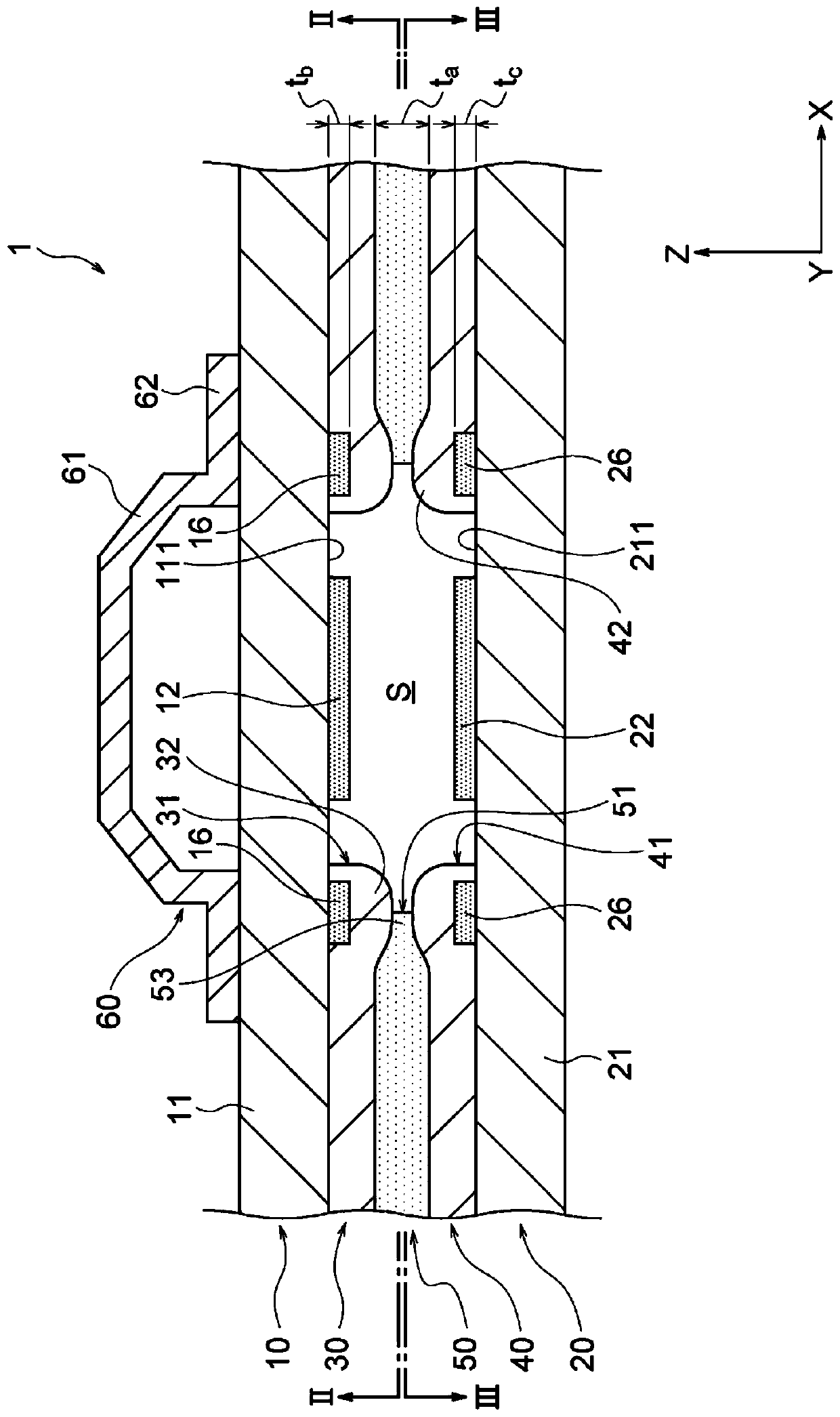
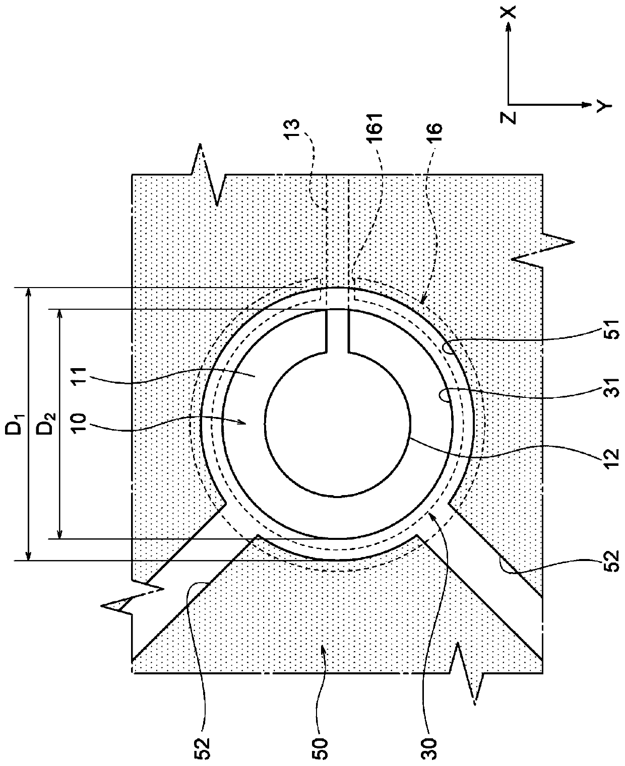
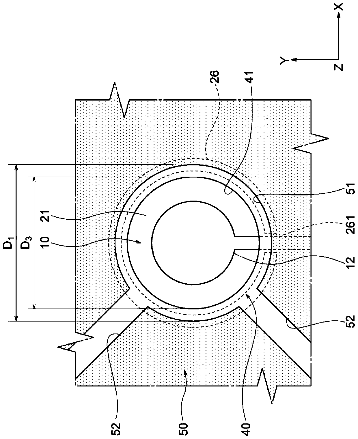
[0035] figure 1 is a cross-sectional view showing a contact portion of the membrane switch 1 according to the first embodiment of the present invention, figure 2 is along figure 1 The sectional view of the II-II line, image 3 is along figure 1 Sectional view of line III-III.

[0036] Such as Figure 1 ~ Figure 3 As shown, the membrane switch 1 of this embodiment includes the upper electrode sheet 10, the lower electrode sheet 20, the adhesive layer 50, and the rubber dome 60 as a pressing member. The upper electrode sheet 10 includes an upper substrate 11 , an upper electrode 12 , and an upper insulating layer 30 . In addition, the lower electrode sheet 20 includes a lower base material 21 , a lower electrode 22 , and a lower insulating layer 40 .

[0037] In this membrane switch 1 , the upper insulating layer 30 is formed on the lower surface 111 of the upper ...


PUM

PropertyMeasurementUnit
thicknessaaaaaaaaaa

Abstract

This switch 1 is provided with: an upper electrode sheet 10 which comprises an upper electrode 12; a lower electrode sheet 20 which faces the upper electrode sheet and comprises a lower electrode 22;and an adhesive layer 50 which has an opening 51 where the electrodes face each other, and which bonds the electrode sheets with each other. The upper electrode sheet comprises: an upper substrate 11on which the upper electrode is formed; an upper insulating layer 30 which is provided between the upper substrate and the lower electrode sheet, while having an opening 31 at a position correspondingto the upper electrode, and which is bonded to the lower electrode sheet by means of the adhesive layer; and an upper base part 16 which is provided between the upper substrate and the upper insulating layer, and which is arranged so as to overlap an edge 53 of the opening of the adhesive layer. The upper insulating layer bulges toward the lower electrode sheet by means of the upper base part ina portion corresponding to the upper base part.

Description

technical field [0001] The present invention relates to switches. [0002] With regard to designated countries that allow the citation of references, this specification is incorporated by referring to the content described in Japanese Patent Application No. 2017-120714 filed in Japan on June 20, 2017, and made a part of the description of this specification. Background technique [0003] It is known to have upper and lower electrode sheets; and a pad arranged between the upper and lower electrode sheets to form a predetermined interval between the upper and lower electrode sheets, and a switch in which the upper and lower electrode sheets and the pad are bonded via an adhesive (for example, refer to patent Literature 1). [0004] Patent Document 1: Japanese Patent Laid-Open No. 2002-358852 [0005] In the switch described above, an opening for enabling the upper and lower electrodes to come into contact with the pad is formed, and the sticker is provided around the opening...

Claims


Application Information

Patent Timeline
Patent Type & Authority Applications(China)
IPC IPC(8): H01H13/704
CPCH01H13/703H01H13/704H01H13/81H01H13/82H01H2207/004H01H2209/01H01H2209/012H01H2211/004H01H2213/01H01H2227/006H01H2227/01H01H2227/02H01H2227/024H01H13/10
Inventor 松岛康介田中涉立川泰之
Owner THE FUJIKURA CABLE WORKS LTD
Why Eureka
Try Eureka