
System for overvoltage protection

A technology of surge protection and transformers, applied in the protection of overvoltage response, emergency protection circuit device for limiting overcurrent/overvoltage, emergency protection circuit device, etc., can solve high peak voltage, insurance damage, Unable to determine the remaining voltage and other issues

Inactive Publication Date: 2003-09-17
KONINK KPN NV
View PDF3 Cites 16 Cited by
  • Summary
  • Abstract
  • Description
  • Claims
  • Application Information

AI Technical Summary

Problems solved by technology

[0013] The disadvantage of using spark gap elements or spark gaps connected between phase and neutral conductors is that the residual voltage makes it difficult to determine and usually has very large values
Also, the spark gap will hold an undetermined residual voltage, depending on the rise time of the lightning pulse, it could be 2.5-4kV, which is too much for low voltage gear
Also, the spark gap element will cause a short circuit and thus create a net corollary current which will almost certainly blow out the fuse (of the power supplier)
Failure of the fuse can result in operational downtime of the unit powered by the transformer
[0014] It is an object of the present invention to provide a surge protection system for low voltage applications which does not have the disadvantages of the known systems described above; it is also an object of the present invention to provide a solution to the problem described above in the preamble The stated power supply has such a limited path to ground and used to shunt the discharge charge that the peak voltage that occurs is relatively high and falls relatively slowly

Method used


Image

  • System for overvoltage protection
  • System for overvoltage protection
  • System for overvoltage protection

Examples


Embodiment Construction

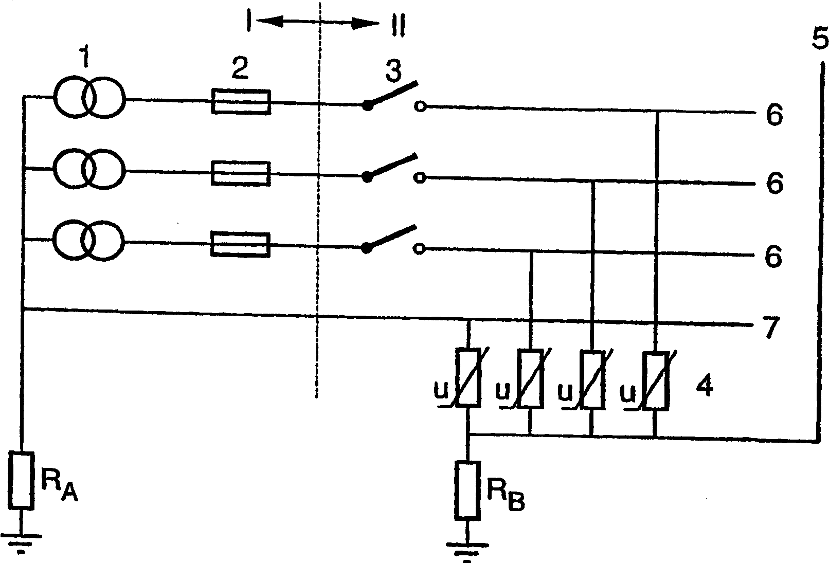
[0035] figure 1 Indicates the state of the art technology, and I indicates the part located in the power supply space. The three windings of the transformer are numbered 1, the secondary winding of the transformer is a star structure, and the neutral point of the star structure is grounded. The impedance between the neutral point and the zero potential point is represented by Ra, and its value is usually very low, such as 0.5Ohm, and the self-inductance is, for example, 5μH. The resistance of the secondary winding of the transformer is usually about 0.01Ω, and the self-inductance is 50μH. In this space, there is also insurance 2.

[0036] The user equipment at part II includes three phase switches 3 . Each (phase and neutral) conductor is connected to a connection 5 after the switch 3 via a surge arrester 4 such as a varistor or varistor or the like. Connection 5 connects to the rack in the switch room (or target). This connection 5 is grounded via a ground conductor havi...


PUM


Abstract

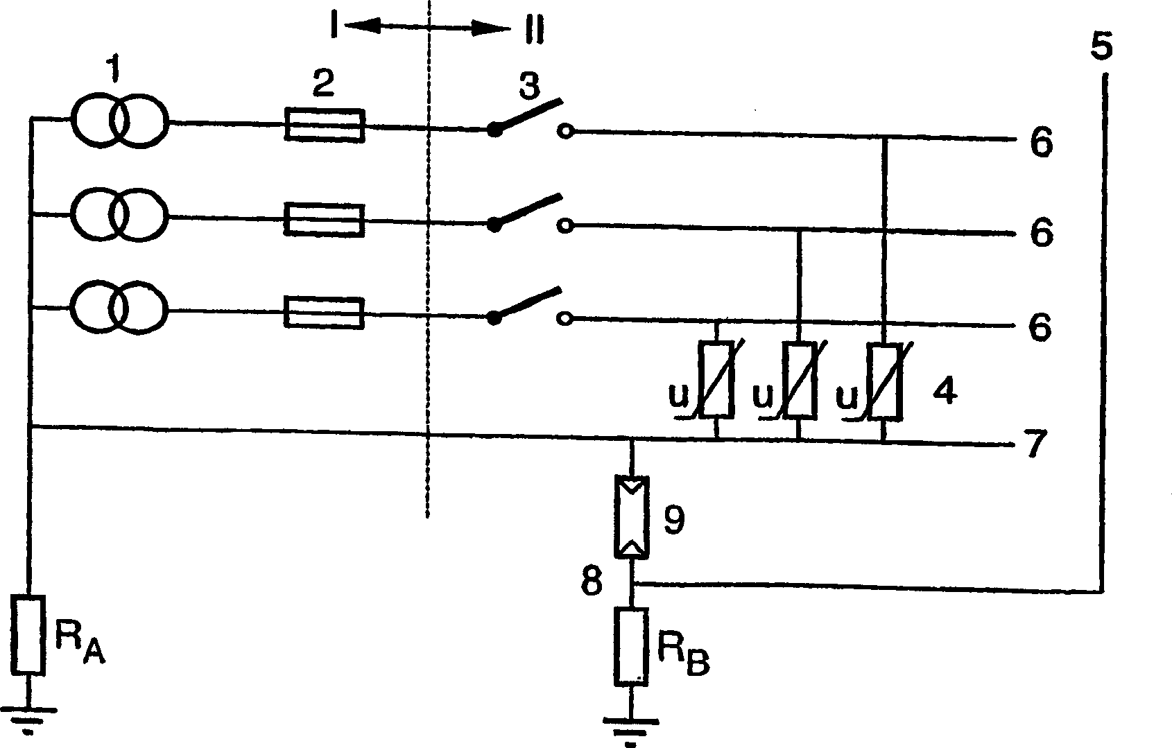
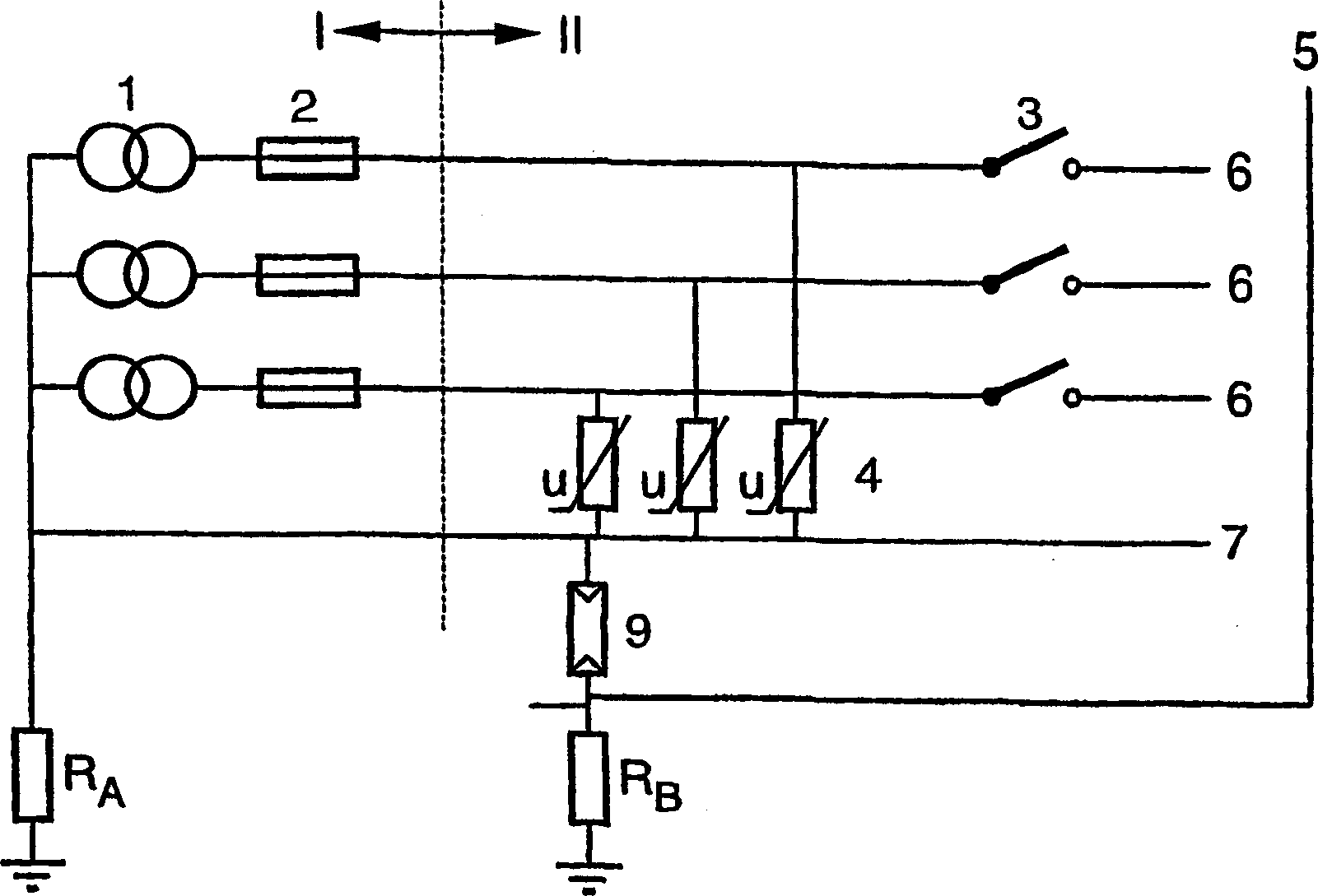
System for surge protection of an object comprising a supply unit, which is connected to the secondary output of an external transformer. The secondary windings (1) of the external transformer are coupled in a star configuration, the star point of the transformer being connected to a downstream neutral conductor (7) and an earth electrode provided near to the transformer. In the supply unit, at least one phase conductor (6) is connected to the neutral conductor (7) by means of a surge protective device of a first type (4), and the neutral conductor (7) is connected to an earth electrode (5) provided near to the supply unit by means of a surge protective device of a second type (9). The surge protective device of the first type (4) comprises a voltage dependent resistor or varistor and the surge protective device of the second type (9) comprises a lightning current arrester or spark gap element.

Description

Background of the invention [0001] The invention relates to a system for lightning and surge protection of objects, in which devices installed are powered. More specifically, the present invention relates to a system for surge protection of an object comprising a power supply unit connected to a secondary output of an external transformer, wherein the secondary winding of the external transformer is coupled in a star configuration, the center of the transformer The neutral point is connected to the downstream neutral conductor and the grounding electrode provided near the transformer. [0002] In particular, the invention can be used as a system for lightning and surge protection of objects installed on a limited area, on the ground or on a building. Examples of such objects include devices equipped with antennas, such as GSM base stations. Surge protection devices for power supply units are generally known. [0003] The protection device according to the present applicatio...

Claims


Application Information

Patent Timeline
Patent Type & Authority Applications(China)
IPC IPC(8): H02H3/22H02H9/04H02H9/06
CPCH02H9/042H02H9/06
Inventor J·T·A·库温霍文M·H·哈特曼T·F·克鲁尔
Owner KONINK KPN NV
Learn More