
Intensified heat exchange tube with intersectional zoomed sections of circle-ellipse

An elliptical section, heat exchange tube technology, applied in heat exchange equipment, tubular elements, lighting and heating equipment, etc., can solve the problems of troublesome design and manufacture of heat exchangers, poor pressure resistance of elliptical tubes, small flow resistance, etc. Good heat transfer enhancement performance, wide application range, small flow resistance effect

Inactive Publication Date: 2003-10-08
TSINGHUA UNIV
View PDF1 Cites 27 Cited by
  • Summary
  • Abstract
  • Description
  • Claims
  • Application Information

AI Technical Summary

Benefits of technology

This patented technology improves on existing methods like spirals or laminar flows without generating too much energy from moving parts. It achieves this through changing shapes and sizes of piping sections, which makes them less prone to damage during operation. Additionally, its effectiveness increases when applied at high temperatures while minimizing coolant usage. Overall, these technical improvements improve efficiency and durability over traditional designs.

Problems solved by technology

Technological Problem addressed in this patents are how to effectively use an improved type of heat transmission technique called "passively” strengthened," without increasing resistances for energy consumption compared to existing methods like other types of heating systems.

Method used


Image

  • Intensified heat exchange tube with intersectional zoomed sections of circle-ellipse
  • Intensified heat exchange tube with intersectional zoomed sections of circle-ellipse
  • Intensified heat exchange tube with intersectional zoomed sections of circle-ellipse

Examples


Embodiment Construction

[0014] The specific structure of the present invention will be described in detail below in conjunction with the accompanying drawings.

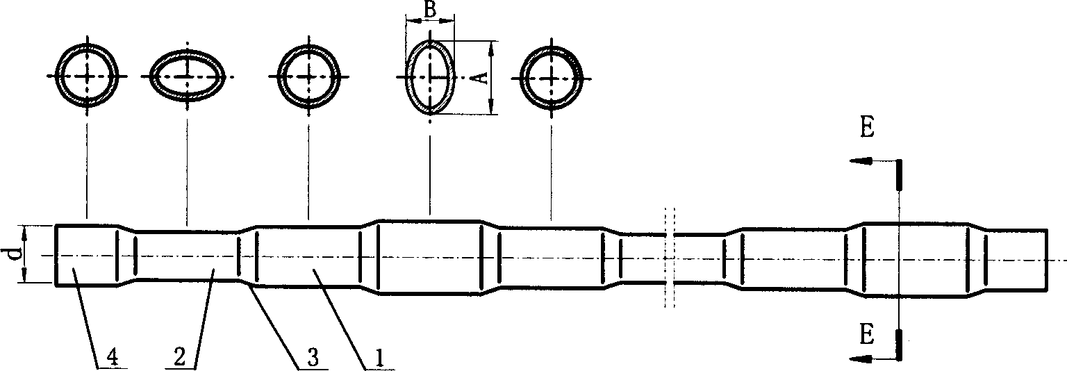
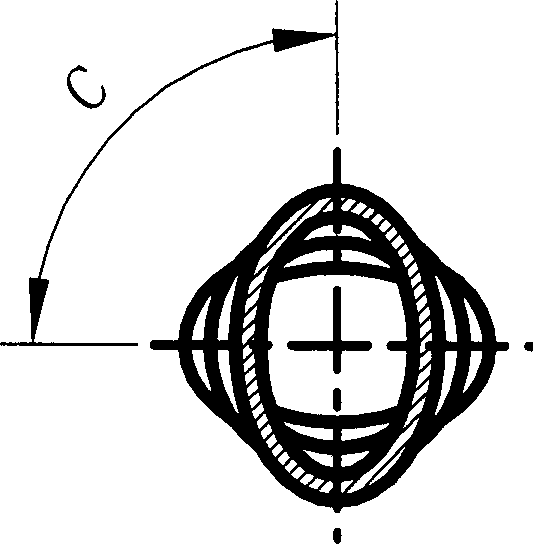
[0015] figure 1 It is a structural schematic diagram of a circle-ellipse section cross-scaling enhanced heat exchange tube provided by the present invention. The enhanced heat exchange tube is composed of several circular tube sections 1, elliptical tube sections 2, circular-elliptical transition sections 3 and inlet circular tube sections 4 at both ends. The length Lc of the round pipe section is determined according to the requirements of pressure resistance, flow resistance, and installation of baffle plates or baffle rods. Generally, Lc / d=0.5~10, where d is the inner diameter of the round pipe. The lengths of each circular pipe section can be equal or unequal. The length Lo of the round tube section at both ends can be 2 to 4 times the thickness of the tube sheet, depending on the needs of its assembly with the tube sheet, and take the...


PUM


Abstract

Round-ellipse section cross convergent-divergent uprated heat exchange tube is composed of several round, and round-ellipse change over sections, the said round and ellipase sections are arrayed in sequence periodically, the ellipse long shafts of adjacent ellipse sections form 1.5-90 deg. angle. Advantages: small flow resistance, velocity field and temperature gradient have better cooperation level, so as to have better heat conduction uprated performance and more convenient for processing baffle boards and rods. This invention can be used either in single phase fluide heat conduction or in flow boiling, flow cooling phase conversion intensifications.

Description


Claims


Application Information

Patent Timeline
Owner TSINGHUA UNIV
Learn More