Arm-tie rotating mechanism

A technology of rotating mechanisms and struts, which is applied in the direction of supporting machines, mechanical equipment, machine tables/supports, etc., and can solve problems such as inapplicability

Inactive Publication Date: 2003-11-19
YAMAHA CORP
View PDF0 Cites 7 Cited by
  • Summary
  • Abstract
  • Description
  • Claims
  • Application Information

AI Technical Summary

Problems solved by technology

[0006] However, in the case of using this stop, it is not practical to force the brace to rotate in the direction in which it becomes erect since if pressure is applied to the base of the brace against the stop, the brace will eventually fall down. , so having to support the pole with one hand is unavoidable
Therefore, this will lead to a problem that the work of lifting the piano cover by two hands cannot be done with two hands.

Method used


Image

  • Arm-tie rotating mechanism
  • Arm-tie rotating mechanism
  • Arm-tie rotating mechanism

Examples


no. 1 example

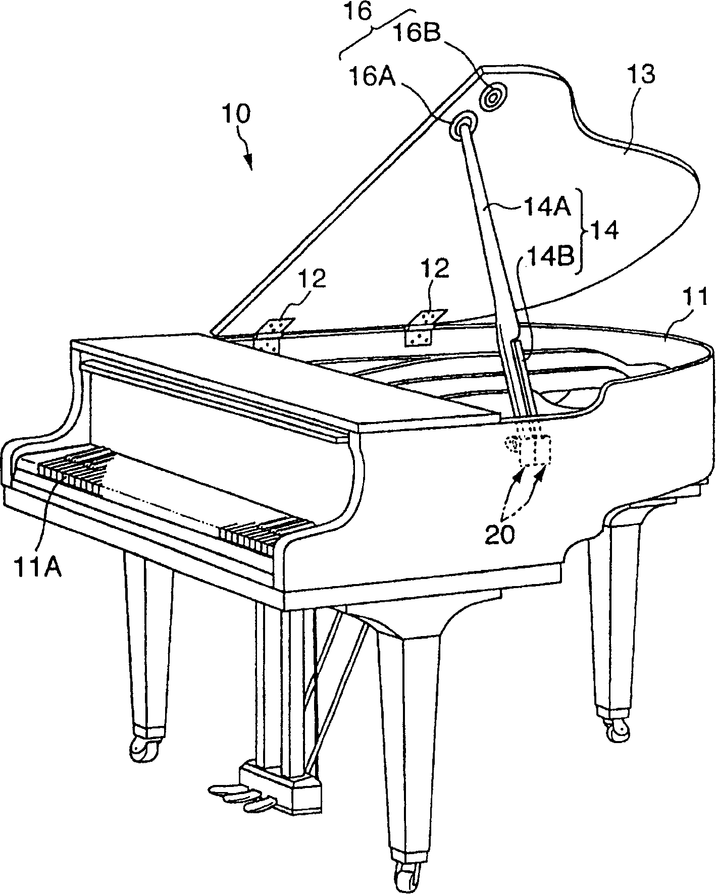
[0026] figure 1 is a schematic perspective view of the grand piano in the first embodiment. In this figure, the grand piano 10 is in the form of opening the top side, and it is composed of the following parts: a piano body 11 having components such as a movement limiting mechanism, and a hinge 12 installed at two positions along one edge of the piano body 11. , be supported on the qin body 11 by these hinges 12 and can make the opening surface (top surface) of the qin body 11 open and close the qin cover 13, be supported on the other side of the qin body 11 (promptly be equipped with hinge 12 position on the opposite side) so as to be able to rotate the strut 14 inside the piano body 11, and hold the jack 16 at the end of this strut 14.

[0027] Jacking hole 16 is arranged on the bottom of piano cover 13, is positioned at the corner area of ​​its free end. These jacks 16 include two jacks 16A and 16B provided along the edge of the front side (keyboard 11A side).

[0028] Ea...


PUM


Abstract

A brace 14 is provided so as to be able to maintain the open position of a lid 13 of a keyboard musical instrument (grand piano) 10, is able to rotate between an erect position that maintains an open position of lid 13 and a collapsed position, and is able to be self-standing in the erect position. A position regulating section 23 is provided between brace 14 and body 11 of grand piano 10 that maintains an angle of rotation of brace 14 at a constant angle.

Description

technical field [0001] The present invention relates to a pole or jack rotation mechanism, in particular to a pole rotation mechanism capable of preventing the cover or top plate of a musical instrument (such as a grand piano) from inadvertently rotating. Background technique [0002] The top of the grand piano body has a lid that can be supported open and closed, and this type of piano has been widely used in the past. Known grand pianos are equipped with arm-like struts which keep the lid open and which struts are pivotable between an upright position and a lowered position. In order to allow the struts to gradually adjust the opening angle of the lid, two or three struts of different lengths are provided. In addition, two sockets respectively corresponding to each of the struts and capable of receiving the ends of these struts are arranged in a row under the piano cover, and each socket is arranged to be aligned with the struts when the cover plane is in the open positio...

Claims


Application Information

Patent Timeline
Patent Type & Authority Applications(China)
IPC IPC(8): F16M11/10G10C1/04G10C3/00G10C3/02
CPCF16M13/02G10C3/02F16M2200/024F16M11/10
Inventor 白柳荣一古木文美
Owner YAMAHA CORP
Why Eureka
Try Eureka