Clamp and element connection device

A technology of clips and mounting components, which is applied in the direction of connecting components, thin plate connections, mechanical equipment, etc., can solve the problems of complex structure of sleeves and pins, increased cost, weak fixing force of mounting components, etc.

Inactive Publication Date: 2004-01-07
EMHART INDUSTRIES INC
View PDF7 Cites 21 Cited by
  • Summary
  • Abstract
  • Description
  • Claims
  • Application Information

AI Technical Summary

Problems solved by technology

This clip has the following structure: Even when the shaft portion of the sleeve is enlarged by using a long connection, the diameter of the shaft portion of the sleeve can be reduced by pulling out the pin, so the structure of the sleeve and the pin is complicated and the cost increases
Moreover, the pre-installation device for the mounting member on the sleeve shaft is three slender fixed claws extending from the flange to the front end of the sleeve shaft, which may get stuck when the sleeve is inserted into the mounting hole of the mounting member, and because The fixing claw is slender, and the fixing force to the mounting member is slightly weak

Method used


Image

  • Clamp and element connection device
  • Clamp and element connection device
  • Clamp and element connection device

Examples


Embodiment Construction

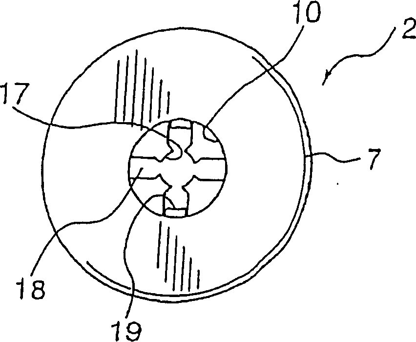
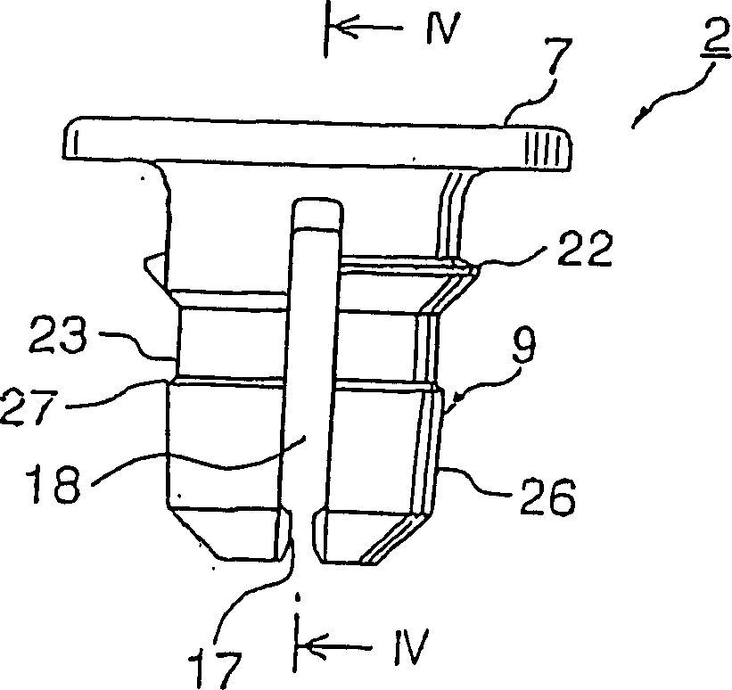
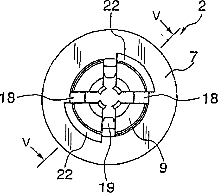
[0019] Embodiments of the present invention will be described below with reference to the drawings. Figure 1 to Figure 9 A clip 1 of an embodiment of the present invention is shown. Clip 1 by Figure 1 to Figure 5 Plastic sleeves shown 2 and Figure 6 and Figure 7 The shown plastic pin 3 consists of two parts. Such as Figure 8 As shown, the clip 1 made of the sleeve 2 and the pin 3 can make the pin 3 be connected to the sleeve 2 at a slightly inserted pre-installation position, and can be installed on the mounting member 5 such as a panel in a pre-installed connection state. When the clip 1 completely presses the pin 3 into the sleeve 2 from the pre-installed position, it moves as follows: Figure 9 Formal fixed position shown. In the connected state of the fixed position, the clip 1 can be used to connect the mounting member 5 such as the panel to the mounted member 6 such as the vehicle body.

[0020] refer to Figure 1 to Figure 5 Details of the sleeve 2 will be ...


PUM


Abstract

To provide a clip easily and temporarily fixed to a fitting member at a low insertion force, fixed thereto at a high retaining force after the temporary fixing, and comprising a pin and a bush. This clip 1 comprises the bush 2 and the pin 3, a bush shaft part 9 is divided into a plurality of legs by a plurality of slits extending to the tip, and an elastic lock jaw 19 projecting radially inward is formed between the slits and a bush flange 7. The tip of the pin shaft part 9 is formed with a lock groove 31 for being locked to the lock jaw 19 in a temporary fixing state and, when the pin shaft part 30 is completely inserted into the bush shaft part 9, the lock groove 31 receives and locks the pin shaft with the tip of the bush shaft part enlarged. The bush shaft part is provided with two lock parts 22 projecting radially outward in positions separated from the bush flange 7 by a length corresponding to the thickness 21 of the fitting hole part of the fitting member 5. The lock parts 22 are formed in diametrically opposed positions into a staged shape of a prescribed circumferential length.

Description

technical field [0001] The present invention relates to a plastic clamp composed of a pin and a sleeve for connecting a mounting member such as a panel to a mounted member such as a vehicle body. Background technique [0002] Plastic clips consisting of pins and sleeves are known for connecting a mounting member such as a panel to a mounted member such as a vehicle body. In US Pat. No. 4,276,806 specification (Japanese Patent Application Laid-Open No. 55-17794), a plastic clip made of a pin and a sleeve is disclosed. The clip can pre-install the sleeve on the panel and other mounting components. In order to connect the mounting component to the mounted component such as the car body, insert the sleeve into the mounting hole of the mounted component, and insert the pin into the sleeve. The diameter of the front end of the sleeve shaft is expanded, and the mounting member and the mounted member are connected with the expanded sleeve shaft and the sleev...

Claims


Application Information

Patent Timeline
Patent Type & Authority Applications(China)
IPC IPC(8): F16B19/10F16B5/10
Inventor 中谷友彦
Owner EMHART INDUSTRIES INC
Why Eureka
Try Eureka