
Contact grid array system

a grid array and contact technology, applied in the field of elastic electric contacts, can solve the problems of increasing the electrical, reliability requirements of these electrical contacts, the inability to make separable electrical contacts with contacts of miniature electronic circuits, and the inability to meet the requirements of electrical and reliability, and no particular contact design appears to provide all the properties required

Inactive Publication Date: 2007-06-21
NEOCONIX INC
View PDF99 Cites 15 Cited by
  • Summary
  • Abstract
  • Description
  • Claims
  • Application Information

AI Technical Summary

Benefits of technology

"The patent text describes a method for making elastic electric contacts using a manufacturing process that results in flexible design and performance of the contacts. The technical problem addressed is the difficulty in making reliable electrical connections between microcircuits and the rest of an electronic system, as no particular contact design meets all of the requirements for such connections. The invention provides a solution by incorporating a method for forming an interposer, which is a type of contact that can be used in system assembly, device testing, and wafer probing. The invention also includes a variety of different contact designs that can be used in various applications."

Problems solved by technology

The ability to make separable electrical contact with contacts of miniature electronic circuits has become more problematic as the mechanical, electrical, and reliability requirements of these electrical contacts become more demanding.
The problem for the industry, however, is that no particular contact design appears to provide all of the properties required, even where specially designed contact elements are used in specific applications.
None of the existing contacts can meet all of the design criteria.

Method used


Image

  • Contact grid array system
  • Contact grid array system
  • Contact grid array system

Examples


Embodiment Construction

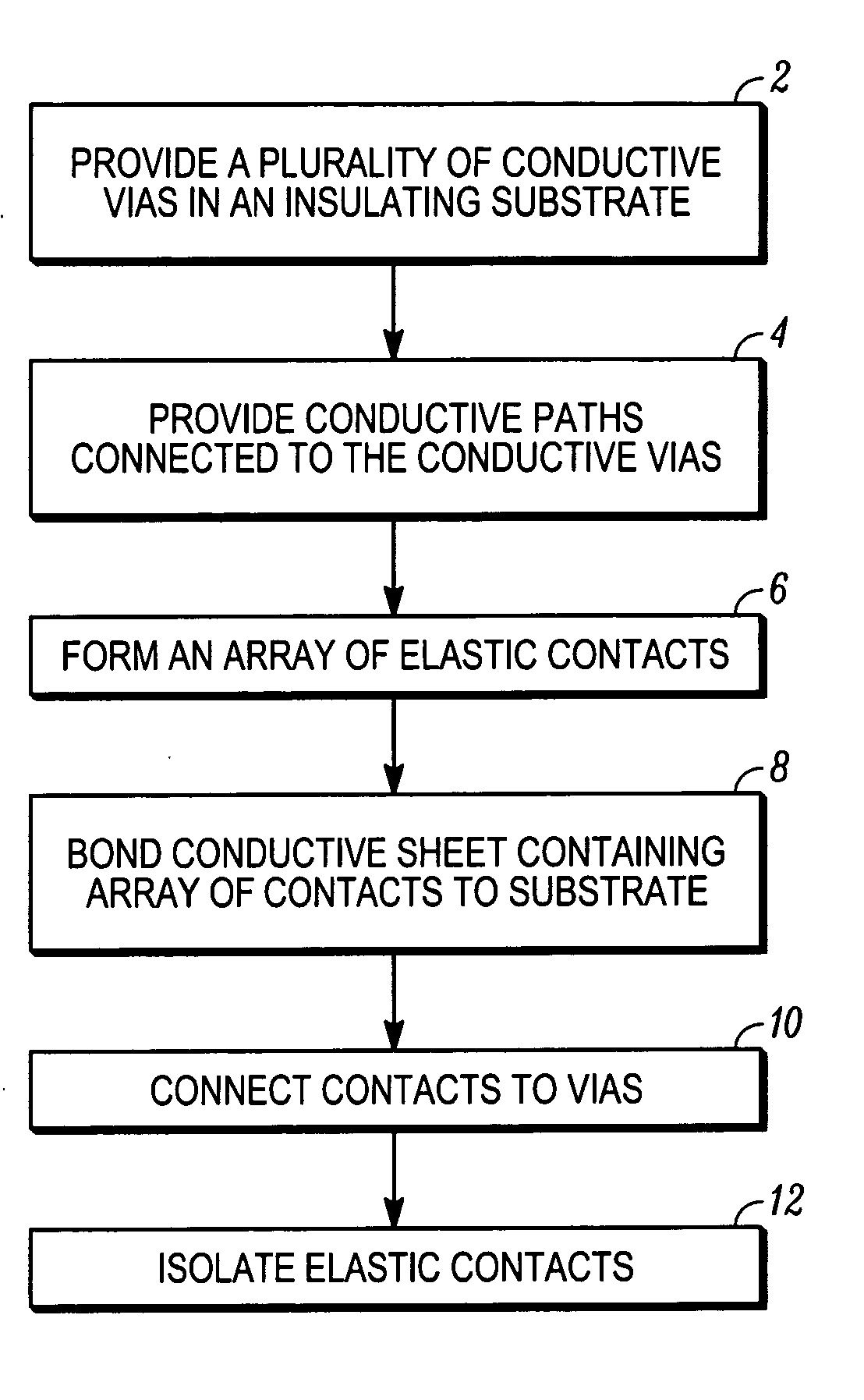
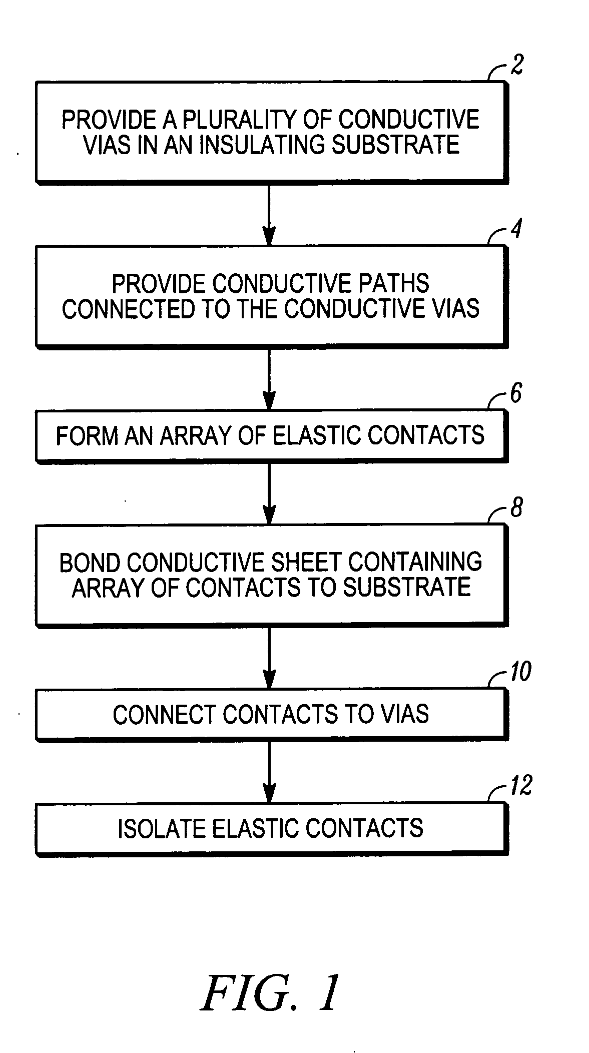
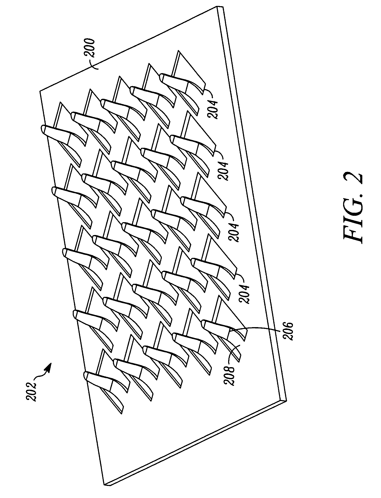
[0053] Aspects of the present invention are related to methods for fabricating electrical connectors by lithographic patterning of metallic layers to form an array or arrays of contact elements. The metallic layers can be applied to a connector substrate before patterning to form the contact elements, or can be free standing layers that are subjected to patterning before joining to the connector substrates. In general, the contacts can be formed from a single layer of metallic material, but can also be formed from multiple layers of the same material, or of different materials, in which one or more layers can be added to the contacts after a metallic layer is patterned to form a contact array. Connectors formed by these methods include substrates having a contact array disposed on a single side, or having contact arrays disposed on both sides, such as interposers.

[0054] Connector elements and interposer layers fabricated according to aspects of the present invention can be produced...


PUM


Abstract

A scalable, low cost, reliable, compliant, low profile, low insertion force, high-density, separable and reconnectable connector for high speed, high performance electronic circuitry and semiconductors. The electrical connector can be used to make, for example, electrical connections from components such as a Printed Circuit Board (PCB) to another PCB, MPU, NPU, or other semiconductor device. A normalized working range for an array of elastic contacts of the interposer can be about 0.2 to 1.0. A reversible normalized working range is maintained through multiple connections and reconnections using a highly elastic material for the contact arms. In one aspect, a first electrical component having a first array pitch can be connected to a second electrical component having a second array pitch.

Description

[0001] This application is a continuation-in-part of U.S. patent application Ser. No. 10 / 412,729, filed Apr. 11, 2003, and is a continuation in part of U.S. patent application Ser. No. 10 / 731,213 filed Dec. 8, 2003, which are hereby incorporated by reference in their entirety.BACKGROUND [0002] 1. Field of the Invention [0003] This invention pertains to elastic electric contacts made by processes for making electrical contacts using manufacturing techniques that result in flexibility in design and performance of the contacts. [0004] 2. Background of the Invention [0005] The ability to make separable electrical contact with contacts of miniature electronic circuits has become more problematic as the mechanical, electrical, and reliability requirements of these electrical contacts become more demanding. Nano springs, pogo pins, micro springs, and other miniature contact devices have been developed to deal with the problem of making reliable electrical contact between a microcircuit and...

Claims


Application Information

Patent Timeline
Patent Type & Authority Applications(United States)
IPC IPC(8): H01R12/00
CPCH01R4/04H01R12/57H01R13/2407H05K3/326H05K3/4015H05K3/4092H01R12/52
Inventor WILLIAMS, JOHN DAVID
Owner NEOCONIX INC
Learn More