Low insertion force seating grommet assembly

a seating grommet and low insertion force technology, applied in the field of seating grommets, can solve the problem of becoming more difficult to find the room necessary to exert such pulling force, and achieve the effect of reducing the seating for

Active Publication Date: 2005-11-22
OSRAM SYLVANIA INC
View PDF20 Cites 15 Cited by
  • Summary
  • Abstract
  • Description
  • Claims
  • Application Information

AI Technical Summary

Benefits of technology

[0004]It is another object of the invention to enhance the use of seating grommets.
[0006]Still another object of the invention is the reduction of the seating force while substantially preventing the grommet from being accidentally pulled to far through the opening it is meant to seal.

Problems solved by technology

As the areas in which these grommets have been employed have been reduced in size (for example, in automobiles) it has become more difficult to find the room necessary to exert such pulling force.

Method used


Image

  • Low insertion force seating grommet assembly
  • Low insertion force seating grommet assembly
  • Low insertion force seating grommet assembly

Examples


Embodiment Construction

[0014]For a better understanding of the present invention, together with other and further objects, advantages and capabilities thereof, reference is made to the following disclosure and appended claims taken in conjunction with the above-described drawings.

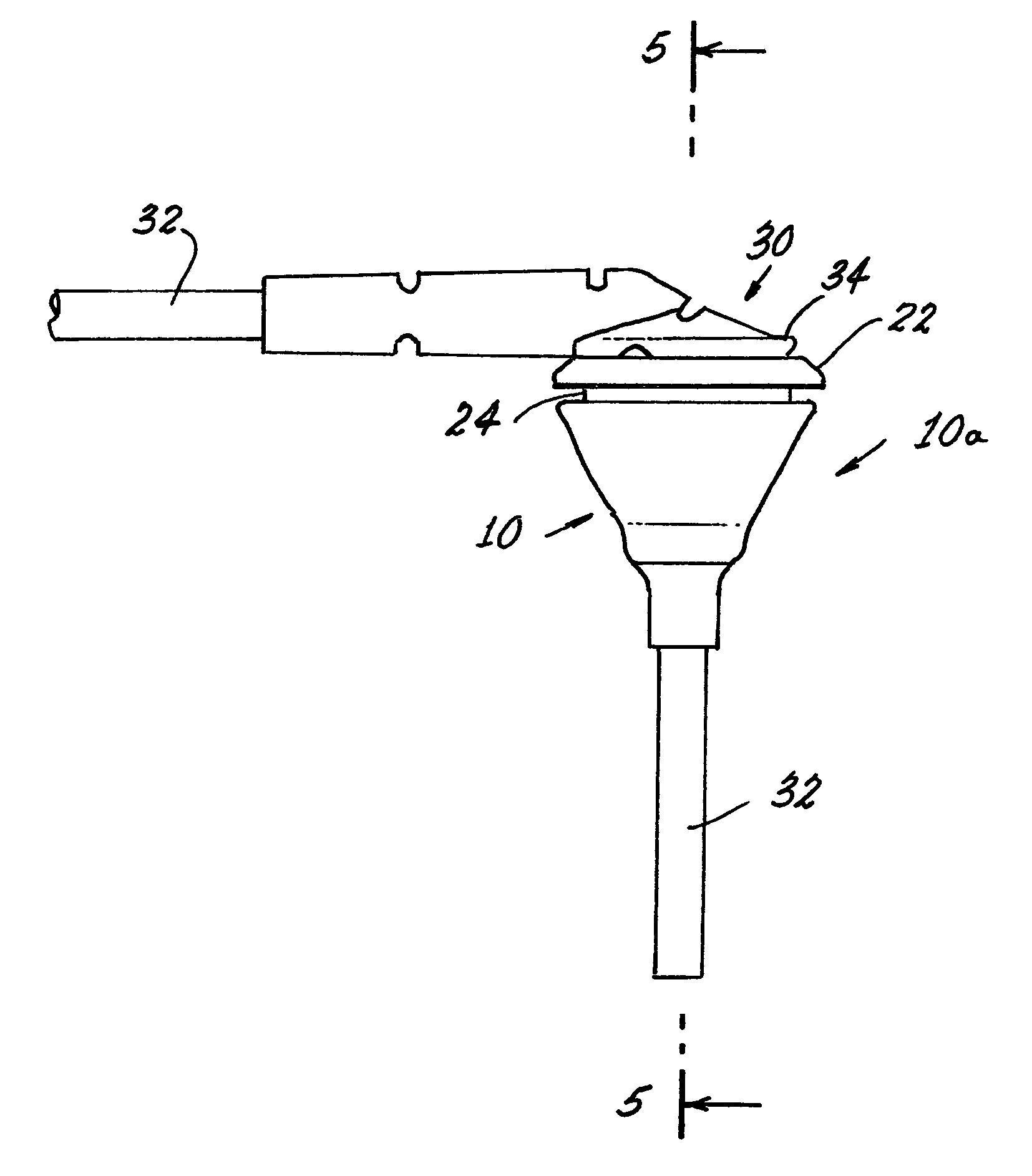
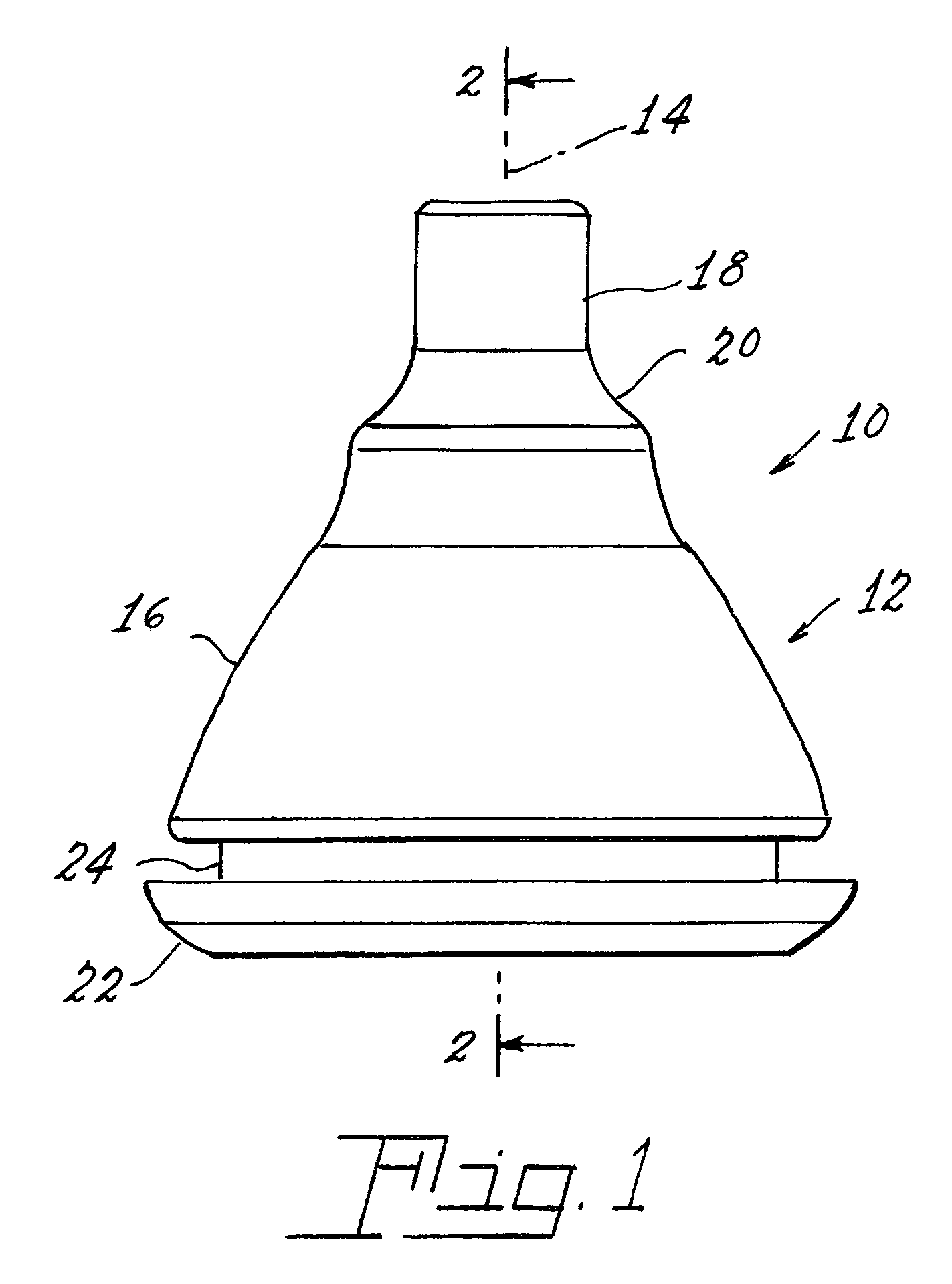
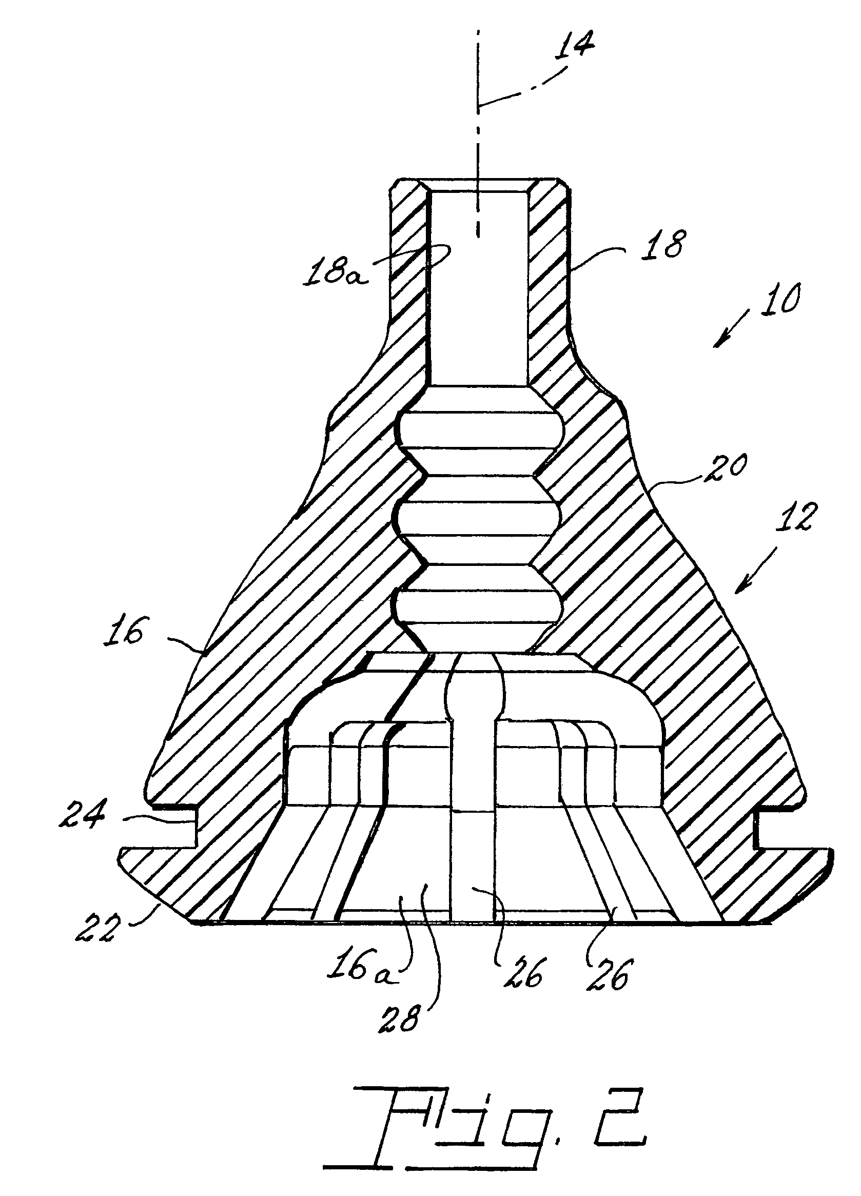
[0015]Referring now to the drawings with greater particularity; there is shown in FIGS. 1–4 a low insertion force seating grommet 10 comprising a hollow body 12 arrayed along a longitudinal axis 14. The body 12 has a wide end 16 and a narrow end 18 connected by an intermediate portion 20. The narrow end 18 has a cylindrical aperture 18a therethrough and the wide end 16 has a cup-shaped aperture 16a. A flange 22 surrounds the wide end 16 and is provided with a wall-opening engaging portion 24. Longitudinally extending relief grooves 26 are formed on the internal surface 28 of the cup-shaped aperture 16a and extend from the outer edge of the wide end 16 to the bottom or terminal area of the cup-shaped aperture 16a.

[0016]While vari...


PUM


Abstract

A low insertion force seating grommet assembly (10a) has a hollow body (12) arrayed along a longitudinal axis (14). The body (12) has a wide end (16) and a narrow end (18) connected by an intermediate portion (20). The narrow end (18) has a cylindrical aperture (18a) and the wide end (16) has a cup-shaped aperture (16a). A flange (22) surrounds the wide end (16) and is provided with a wall-opening engaging portion (24). Longitudinally extending relief grooves (26) are formed on the internal surface (28) of the cup-shaped aperture (18a). A cable (32) is frictionally engaged in the cylindrical aperture and penetrates the cup-shaped aperture. A cover (30) closes the cup-shaped aperture. The cable enters the cover along the longitudinal axis and exits the cover at an angle of 90 degrees relative to the longitudinal axis.

Description

TECHNICAL FIELD[0001]This invention relates to seating grommets and more particularly to seating grommets having a reduced pull-through or seating force.BACKGROUND ART[0002]Prior art seating grommets have comprised relatively massive, solid, hemispherical components of a flexible material such as rubber. See, for example, U.S. Pat. No. 2,225,472. The grommet would be provided with a groove for engaging a wall, usually combined with a flange for inhibiting pull-through. Such grommets frequently required a setting force of up to 75 pounds. As the areas in which these grommets have been employed have been reduced in size (for example, in automobiles) it has become more difficult to find the room necessary to exert such pulling force. Improved grommets having a lesser setting force have been proposed wherein the flexible portion is substantially hollow. Examples of the latter grommets are shown U.S. Pat. Nos. 2,375,373; 3,244,802; 3,372,960; 4,041,241; 4,685,173; 5,337,447; 5,452,494; a...

Claims


Application Information

Patent Timeline
Patent Type & Authority Patents(United States)
IPC IPC(8): F16L5/00H02G3/18B60R16/02F16L5/10H02G3/08H02G15/013
CPCB60R16/0222F16L5/10H02G15/013H02G3/083Y10T16/05Y10T16/063
Inventor SANROMA, JOHN P.FREEMAN, JR., GLENN R.
Owner OSRAM SYLVANIA INC
Why Eureka
Try Eureka