
Method and apparatus for power outlet and plug having low-insertion-force connector

a technology of low-insertion force and power outlet, which is applied in the direction of coupling device connection, coupling contact member, coupling/disengagement part, etc., can solve the problems of unplugged before the plug, cord or outlet is damaged, etc., and achieves high contact force, high compressive force, good wiping

Inactive Publication Date: 2009-05-19
MECHANICAL ANSWERS
View PDF16 Cites 14 Cited by
  • Summary
  • Abstract
  • Description
  • Claims
  • Application Information

AI Technical Summary

Benefits of technology

[0014]The present invention provides a method and apparatus to address the problems of simultaneously providing low or zero insertion force, while providing high compressive force and good wiping action as the electrical contact is being made and used. Further, some embodiments provide the high contact force without actually locking the plug to the outlet, in order that if the plug or power cord is pulled on, it will eventually come unplugged before the plug, cord, or outlet is damaged. One advantage of some embodiments of the present invention is that it allows for the utilization of the conventional three-prong power plug.
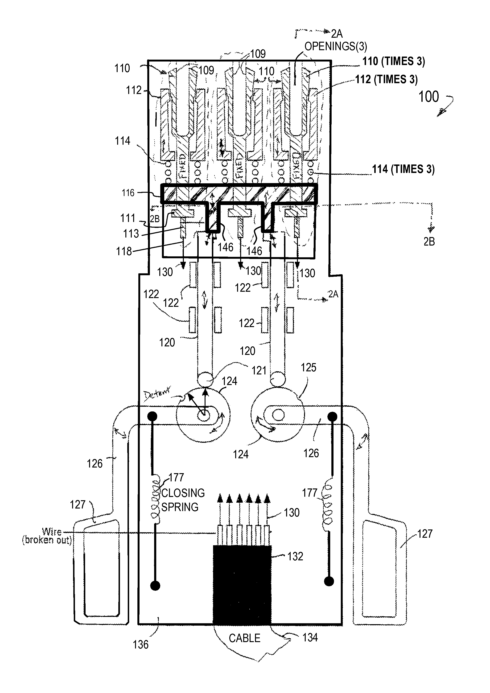
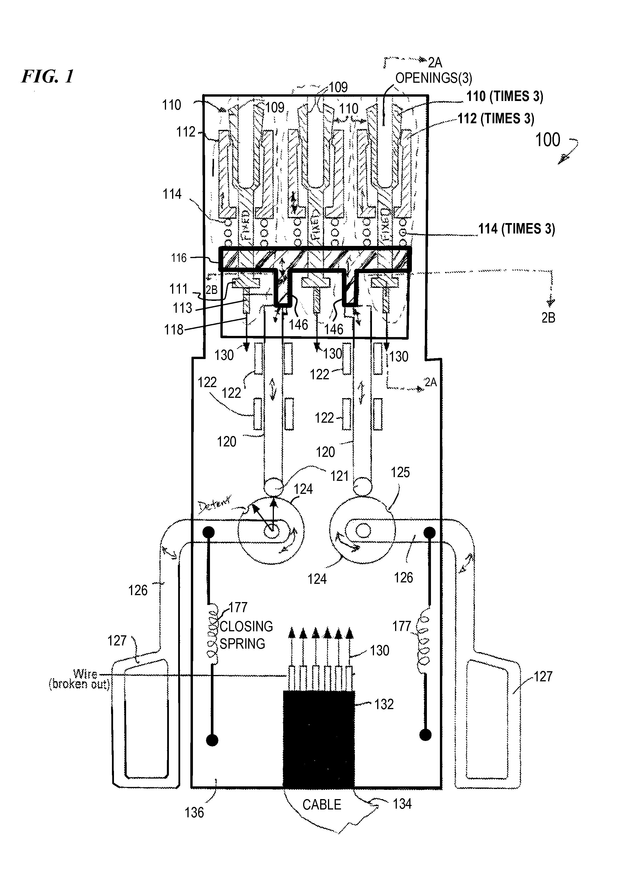
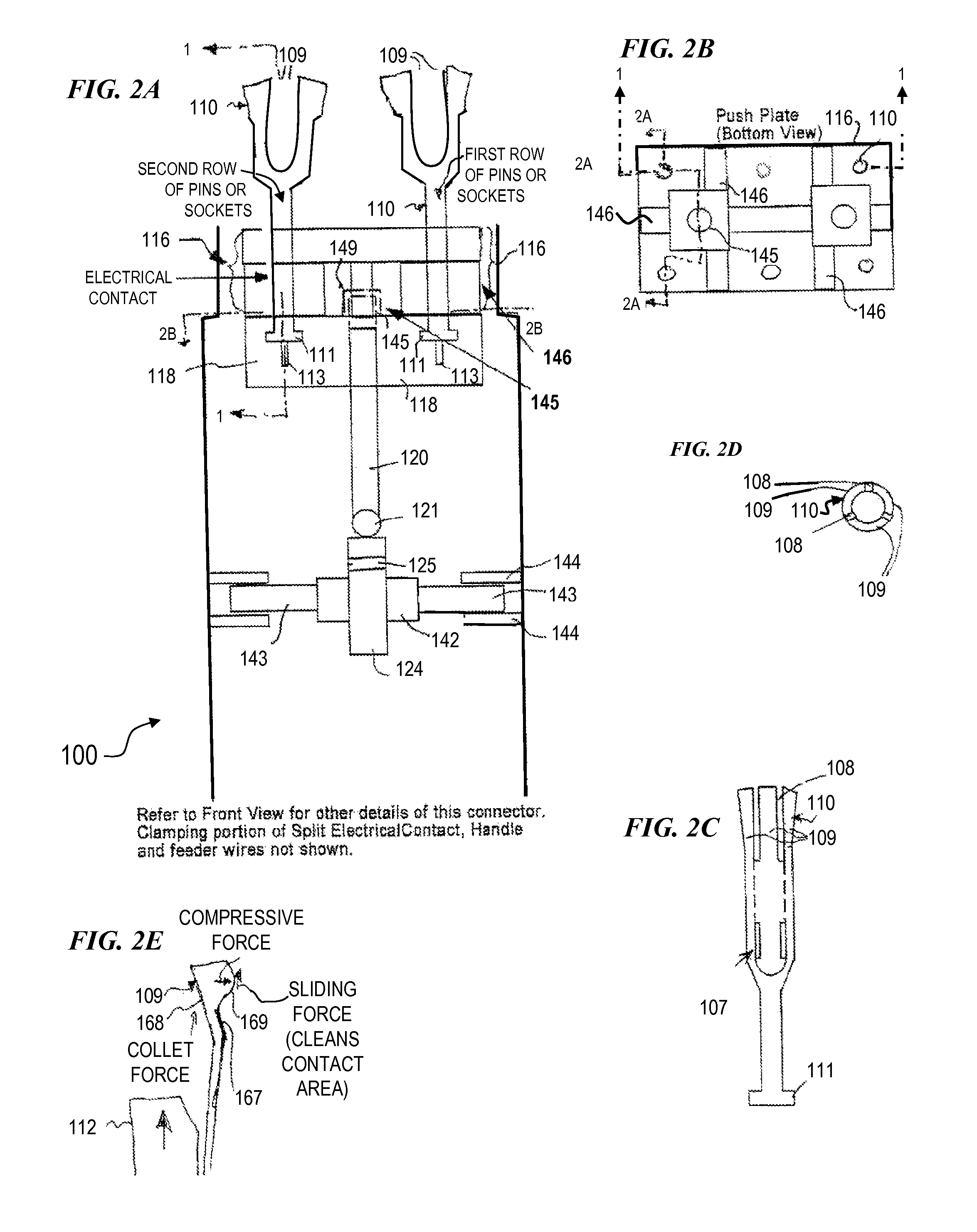
[0015]In some embodiments, the present invention provides an independently tightening collet surrounding each socket for each of a plurality of corresponding prongs, wherein the collet is loosened for normal (low-insertion-force) insertion and withdrawal of the plug from the outlet. Once the plug is inserted, the collet is tightened, providing a high-contact force to lower the contact resistance and to help keep the plug from coming unplugged. In some embodiments, the plug is not “locked”, in that a tension force (e.g., from the vehicle pulling away, or from a person pulling on the cord hard enough) pulling on the plug will overcome the contact force at a point before the plug or outlet is damaged, and the plug is allowed to come unplugged. In some embodiments, engaging the collet will also provide a wiping or sliding motion between the prong and socket for each connection, thus wiping at least some dirt or corrosion away and providing a lower-resistance better electrical contact.
[0017]In some embodiments, the outlet of the present invention includes a plurality (e.g., three, in some embodiments) of recessed fixed prongs (male connectors), and the plug includes a corresponding number of sockets each having a tightenable, independent collet that can be activated to tighten onto its respective prong upon manual activation by the user (e.g., by pushing or pulling on one or more activation handles). In some embodiments, each collet has its own spring that imparts a predetermined amount of contact force, resulting in a reliable, repeatable force being applied on each electrical contact. In some embodiments, each socket has a plurality of fingers (e.g., three fingers arranged 120 degrees from each other in a circle around the prong) that, when they are squeezed by the collet, impart a slight wiping action against the sides of the prong. In other embodiments, no wiping action is applied, and the fingers simply tighten on the prong. By placing the prongs in a recessed fixed configuration on the outlet portion of the connection, there are no moving parts on the outlet (which is harder and more costly to repair or replace), and the moving parts in the power cord can be replaced more inexpensively.

Problems solved by technology

Further, some embodiments provide the high contact force without actually locking the plug to the outlet, in order that if the plug or power cord is pulled on, it will eventually come unplugged before the plug, cord, or outlet is damaged.

Method used


Image

  • Method and apparatus for power outlet and plug having low-insertion-force connector
  • Method and apparatus for power outlet and plug having low-insertion-force connector
  • Method and apparatus for power outlet and plug having low-insertion-force connector

Examples


Embodiment Construction

[0052]Although the following detailed description contains many specifics for the purpose of illustration, a person of ordinary skill in the art will appreciate that many variations and alterations to the following details are within the scope of the invention. Accordingly, the following preferred embodiments of the invention are set forth without any loss of generality to, and without imposing limitations upon the claimed invention.

[0053]In the following detailed description of the preferred embodiments, reference is made to the accompanying drawings that form a part hereof, and in which are shown by way of illustration specific embodiments in which the invention may be practiced. It is understood that other embodiments may be utilized and structural changes may be made without departing from the scope of the present invention.

[0054]The leading digit(s) of reference numbers appearing in the Figures generally corresponds to the Figure number in which that component is first introduc...


PUM


Abstract

In some embodiments, the present invention provides an independently tightening collet surrounding each socket for each of a plurality of corresponding high-electrical-power prongs, wherein the collet is loosened for normal (low-insertion-force) insertion and withdrawal of the plug from the outlet. Once the plug is inserted, the collet is tightened, providing a high-contact force to lower the contact resistance and to help keep the plug from coming unplugged. In some embodiments, the plug is not “locked”, in that a tension force pulling on the plug will overcome the contact force at a point before the plug or outlet is damaged, and the plug is allowed to come unplugged. In some embodiments, engaging the collet will also provide a wiping or sliding motion between the prong and socket for each connection, thus wiping at least some dirt or corrosion away and providing a lower-resistance better electrical contact.

Description

CROSS-REFERENCE TO RELATED APPLICATIONS[0001]This invention claims benefit of U.S. Provisional Patent Application 60 / 782,041 filed Mar. 13, 2006, which is hereby incorporated by reference in its entirety.FIELD OF THE INVENTION[0002]This invention relates to the field of electric-power outlets, and more particularly to a method and apparatus for an electrical power outlet and mating plug having low- or zero-insertion force required, and having a contact-tightening mechanism to provide a highly reliable, low-resistance, high-current-capable, and / or lockable connection.BACKGROUND OF THE INVENTION[0003]Vehicles often need to obtain power (e.g., 110-volt or 220-volt AC, or sometimes 12 or 24-volt DC) from a land-based supply (e.g., by connection to the electrical utility power grid). Some conventional vehicles include a conventional 110-volt power cord running from the vehicle and having a conventional three-prong NEMA-standard plug on the end (National Electrical Manufacturers Associati...

Claims


Application Information

Patent Timeline
IPC IPC(8): H01R13/15H01R13/62
CPCH01R13/193H01R13/639H01R2201/26
Inventor LEMAIRE, CHARLES A.MAXWELL, MARIAN D.DRAGGIE, RAYMOND Q.MAXWELL, SCOTT D.
Owner MECHANICAL ANSWERS
Learn More