Straightening and winding device applied to tire bead wire production

A technology of winding device and bead steel wire, which is applied in the directions of transportation and packaging, grinding machine tool parts, and conveying filamentous materials, etc. It can solve the problems of single function, simple structure, and no shock-absorbing structure, etc. Tightness, guarantee of applicability, effect of improving torsion resistance

Pending Publication Date: 2021-06-04
JIANGSU SHENGDA TECH
View PDF23 Cites 0 Cited by
  • Summary
  • Abstract
  • Description
  • Claims
  • Application Information

AI Technical Summary

Problems solved by technology

[0006] The existing design has a simple structure and a single function, which cannot achieve a good straightening effect and does not have a shock-absorbing structure. The vibration during use will affect the winding effect of the bead wire

Method used


Image

  • Straightening and winding device applied to tire bead wire production
  • Straightening and winding device applied to tire bead wire production
  • Straightening and winding device applied to tire bead wire production

Examples


Embodiment 1

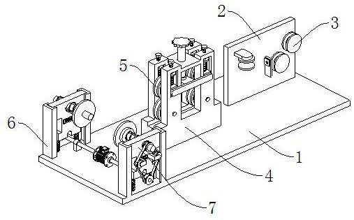
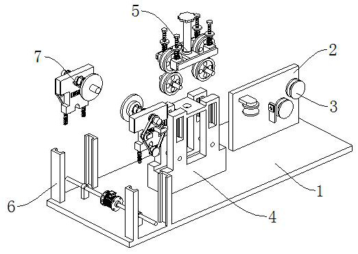
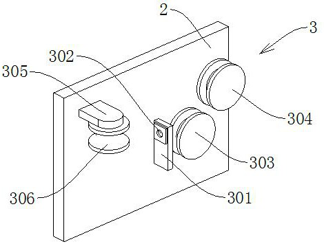
[0030] see Figure 1-3, a straightening and winding device applied to the production of bead wires, comprising a mounting base 1, a mounting plate 2, a fixing frame 4 and a mounting frame 6, the mounting plate 2 is fixedly connected to the mounting base 1, and the mounting plate 2 is connected to There is a steel wire dephosphorization mechanism 3, and the fixed frame 4 is fixedly connected to the middle position of the installation base 1, and the steel wire straightening mechanism 5 is connected to the fixed frame 4; the installation frame 6 is fixedly connected to the end of the installation base 1 away from the installation plate 2, and the installation frame 6 is connected with a driving winding device 7, and the driving winding device 7 includes a driving mechanism and a winding mechanism.

[0031] The steel wire dephosphorization mechanism 3 includes a first connecting plate 301, a first vertical fixed pulley 303 and a second vertical fixed pulley 304, the first connect...

Embodiment 2

[0034] see Figure 4-5 The difference in connection with the basis of Embodiment 1 is that the wire straightening mechanism 5 includes a fixed straightening wheel 501, and the fixed straightening wheel 501 is rotatably connected to the bottom of the fixed frame 4, and the fixed frame 4 is vertically provided with a first Limiting groove 502, vertical sliding connection in the first limiting groove 502 is movable block 503, movable straightening wheel 504 is connected with rotation between movable block 503, and linkage adjustment rod 505 is fixedly connected on the outer wall of movable block 503, linkage adjustment A first fixing plate 506 is fixedly connected between the rods 505 , and a first thread adjusting rod 507 is rotatably connected to the first fixing plate 506 .

[0035] The top of the first fixed plate 506 is provided with a second fixed plate 508, the second fixed plate 508 is fixedly connected with the fixed frame 4, and the first thread adjusting rod 507 is scr...

Embodiment 3

[0038] See 6, based on Examples 1-2 but differing in that,

[0039] The driving mechanism includes a biaxial servo motor 701, which is fixedly installed on the installation base 1, the output shaft of the biaxial servo motor 701 is fixedly connected with a connecting shaft 702, and the installation base 1 is also fixedly connected with an auxiliary support frame 703 , the connecting shaft 702 is rotatably connected to the auxiliary supporting frame 703 .

[0040] The winding mechanism includes a damping spring 704, the bottom of which is fixedly connected to the mounting base 1, the top of the damping spring 704 is fixedly connected to the bottom surface of the movable plate 705, and the movable plate 705 is vertically slidably connected to the mounting frame 6. On the movable plate 705, a second limiting groove 706 is horizontally arranged, the end of the connecting shaft 702 away from the biaxial servo motor 701 is fixedly connected with a first belt pulley 707, and the seco...


PUM


Abstract

The invention discloses a straightening and winding device applied to tire bead wire production, and belongs to the technical field of tire bead wire production equipment. The straightening and winding device applied to tire bead wire production comprises a mounting base, a mounting plate, a fixing frame and a mounting frame, the mounting plate is fixedly connected to the mounting base, a steel wire dephosphorization mechanism is connected to the mounting plate, the fixing frame is fixedly connected to the middle of the mounting base, and a steel wire straightening mechanism is connected to the fixing frame; and the mounting frame is fixedly connected to the end, away from the mounting plate, of the mounting base, the mounting frame is connected with a driving winding device, and the driving winding device comprises a driving mechanism and a winding mechanism. The straightening and winding device effectively solves the problems that an existing design structure is simple, the function is single, a good straightening effect cannot be achieved, a damping structure is not arranged, and the tire bead wire winding effect can be affected by vibration in the using process.

Description

technical field [0001] The invention relates to the technical field of bead wire production equipment, in particular to a straightening and winding device applied to bead wire production. Background technique [0002] In the production process of bead wire, since the deformation of the steel wire in the mold is uneven, the uneven deformation will generate residual stress, which can generally be eliminated by tempering and roller straighteners, but sometimes The residual stress cannot be eliminated due to poor straightener or improper adjustment of the straightener, which will affect the straightness of the steel wire. In severe cases, the entire steel wire will be unusable and scrapped. Therefore, in the production process of the bead wire, in order to To better ensure the finished product quality of the bead wire, it is often necessary to straighten the wire before winding the bead wire, and the bead wire straightening and winding device has emerged as the times require. ...

Claims


Application Information

Patent Timeline
Patent Type & Authority Applications(China)
IPC IPC(8): B65H54/553B65H54/44B65H54/70B65H67/04B21F1/02B24B27/033B24B41/04
CPCB65H54/553B65H54/44B65H54/70B65H67/0417B21F1/02B24B27/033B24B41/04B65H2701/36
Inventor 董利明徐一铭
Owner JIANGSU SHENGDA TECH
Why Eureka
Try Eureka