
Dust collection bucket with novel power transmission structure

A technology of power transmission and dust collecting bucket, applied in the direction of suction filter, etc., can solve the problems of poor dust compression effect, reduced working efficiency of vacuum cleaner, inconvenient use, etc., and achieve the effect of good compression effect

Inactive Publication Date: 2012-07-18
NANJING LG PANDA APPLIANCES
View PDF7 Cites 0 Cited by
  • Summary
  • Abstract
  • Description
  • Claims
  • Application Information

AI Technical Summary

Problems solved by technology

The dust compression effect on the barrel wall is poor, which will affect the overall compression efficiency, reduce the working efficiency of the vacuum cleaner, and bring inconvenience to users

Method used


Image

  • Dust collection bucket with novel power transmission structure
  • Dust collection bucket with novel power transmission structure
  • Dust collection bucket with novel power transmission structure

Examples


Embodiment Construction

[0033] The present invention will be described in detail below with reference to the drawings and examples. The same symbols are used for the same components in the present invention as in the prior art.

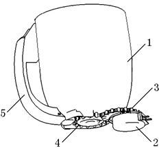
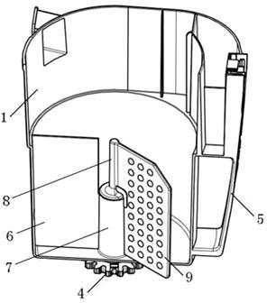
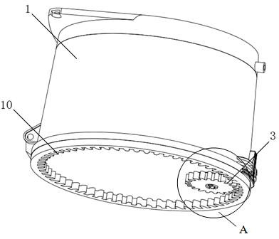
[0034] image 3 It is a three-dimensional view of the appearance of the dust collecting bucket with the novel power conduction structure of the present invention; Figure 4 Yes image 3 The enlarged schematic diagram of part A in the middle; Figure 5 It is a sectional view of the dust collecting bucket with the novel power transmission structure of the present invention. like Figure 3 to Figure 5 As shown, the dust collecting bucket with novel power transmission structure of the present invention includes: a bucket body 1 composed of a bucket bottom 16 and a bucket wall 14 , a baffle plate 13 and a compression plate 9 arranged in the bucket body 1 . The lower side of the barrel bottom 16 is formed with an internal gear 10 meshing with the driving gear 3 and driving th...


PUM


Abstract

The invention relates to a dust collection bucket with a novel power transmission structure, including a bucket body consisting of a bucket bottom and a bucket wall, a baffle arranged inside the bucket body and a compression plate. An inner gear that is meshed with a driving gear and drives the bucket body to rotate is formed on the lower side of the bucket bottom, the compression plate is fixedly connected with the bucket body, and the baffle is fixedly connected onto the wall of a cyclone separator above the bucket body. In the dust collection bucket in the invention, the compression plate is fixedly connected with the bucket body, an inner gear that is meshed with a driving gear and drives the bucket body to rotate is formed on the lower side of the bucket bottom, and the baffle is fixedly connected onto the wall of a cyclone separator above the bucket body. The driving gear drives the inner gear to rotate, and the inner gear drives the bucket body and the compression plate to rotate in order to compress dust, while the baffle does not rotate. In this way, the power of the compression plate comes from the bucket body around, power transferred in this way acts to the outer edge of a circle formed by the rotation of the compression plate, the compression plate is driven to rotate in the tangent direction of the circle, the compression power of the whole compression plate is great, the compression effect is better, and it is more convenient for users to use.

Description

technical field [0001] The invention belongs to the field of vacuum cleaners, and in particular relates to a compression plate fixedly connected with a bucket body, an internal gear is formed on the lower side of the bucket, and the driving gear meshes with the internal gear to drive the internal gear and the bucket body to rotate, and the bucket body drives the compression plate to rotate. Dust bucket with new power transmission structure. Background technique [0002] Vacuum suction is a cleaning and sanitary appliance used to remove dust from floors, carpets, walls, furniture, clothing and various gaps. Vacuum cleaners generally include a vacuum cleaner motor that generates suction from an imported power supply, a motor inlet that forms an air path system, a suction nozzle, a hose, and a dust collection device that collects inhaled matter. [0003] According to the shape of vacuum cleaners, they can be divided into upright vacuum cleaners, horizontal vacuum cleaners and ...

Claims


Application Information

Patent Timeline
Patent Type & Authority Applications(China)
IPC IPC(8): A47L9/10
Inventor 肖宗亮杨小峰
Owner NANJING LG PANDA APPLIANCES
Learn More