Press machine and method for controlling slide of press machine

a press machine and slide technology, applied in the direction of driving apparatus, metal-working machine components, metal-working machinery, etc., can solve the problems of unsuitable inventions for improving formability, inability to obtain an improvement effect, and extremely high price, so as to reduce the inertia mass of the sub-slide to be vibrated, reduce the energy required for vibration, and increase the compression force

Active Publication Date: 2018-12-25
AIDA ENG LTD
View PDF35 Cites 1 Cited by
  • Summary
  • Abstract
  • Description
  • Claims
  • Application Information

AI Technical Summary

Benefits of technology

[0012]The present invention has been made in view of these circumstances, and an object thereof is to provide a press machine capable of applying a large compression force to a mold as well as imparting smooth vibration, which is vibration only in a rectilinear advancing direction of compression, to the mold, and thereby improving the formability, and a method for controlling a slide of a press machine.
[0036]Further, by vibrating the sub-slide (mold) such that the direction of the velocity of the sub-slide during forming of the material is not reversed, the limit drawing ratio can be increased due to the stress relief effect on the material, and favorable press-forming can be performed even under relatively difficult press-forming conditions.

Problems solved by technology

In this case, each mold needs to be provided with the vibration mechanism, which poses a problem of an extremely higher price.
This effect is advantageous in that friction between the mold and the material is reduced, but is more predominantly disadvantageous in that resistance which hinders forming is imparted between the mold and the material, so that no effect for improving the formability can be obtained.
Thus, the inventions are considered to be unsuitable for improving the formability, and their utilization purpose is limited to mere prevention of sticking of the slide.
Further, due to a concern that the mechanism itself can be damaged, it is difficult to practice the inventions in forming applications (for the purpose of friction reduction).
As a result, objects to be formed are also limited, and it is not practical in the first place to apply the invention to press machines.

Method used


Image

  • Press machine and method for controlling slide of press machine
  • Press machine and method for controlling slide of press machine
  • Press machine and method for controlling slide of press machine

Examples


Embodiment Construction

[0048]Hereinafter, preferred embodiments of a press machine and a method for controlling a slide of a press machine according to the present invention will be described in detail in accordance with the attached drawings.

[Embodiment of Press Machine]

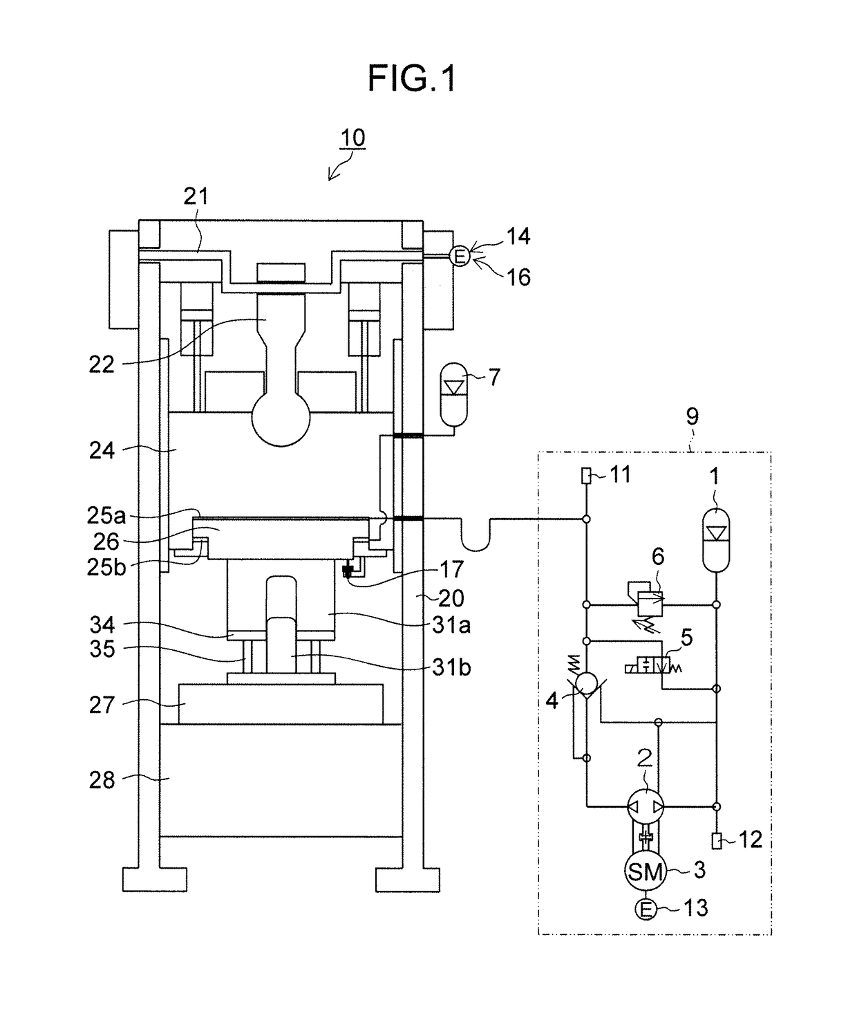
[0049]FIG. 1 is a constitution diagram showing an embodiment of a press machine to which the present invention is applied.

[0050]A press machine 10 shown in FIG. 1 is a crank press which includes a column (frame) 20, a crankshaft 21, a connecting rod 22, a main slide24, a sub-slide 26, a bolster 27 on a bed 28, etc.

[0051]The main slide 24 is guided by a guide provided in the column 20 so as to be reciprocable in a rectilinear advancing direction (in the upper-lower direction in FIG. 1).

[0052]The main slide 24 and the sub-slide 26 constitute a cylinder-piston mechanism (hydraulic cylinder), and the main slide 24 corresponds to a cylinder of the hydraulic cylinder, while the sub-slide 26 corresponds to a piston of the hydraulic cylinder. The...


PUM


Abstract

There is provided a press machine which can apply a large compression force to a mold as well as impart smooth vibration only in a rectilinear advancing direction to the mold, and thereby can improve the press-formability. A main slide and a sub-slide constitute a slide and at the same time a cylinder-piston mechanism. During press-forming, a compression force is transmitted to the sub-slide (an upper mold) through hydraulic pressure applied interlockingly with driving of the main slide, and the sub-slide is vibrated with the hydraulic pressure being periodically changed. Favorable press-forming can be performed even under relatively difficult press-forming conditions, by controlling the vibration such that a vibration frequency of the sub-slide (the upper mold) becomes 9 Hz or higher but 33.3 Hz or lower and a vibration amplitude of the sub-slide becomes 0.05 mm or larger but 0.5 mm or smaller.

Description

BACKGROUND OF THE INVENTION[0001]Field of the Invention[0002]The present invention relates to a press machine and a method for controlling a slide of a press machine, and in particular, to a technology of forming a material while imparting microvibration to a mold.[0003]Description of the Related Art[0004]Conventionally, there has been proposed a vibration press-forming method in which a vibrator is connected to an upper mold of a press machine and a material is pressed between the upper mold and a lower mold by lowering the upper mold while ultrasonically vibrating it with the vibrator (Japanese Patent Application Laid-Open No. 01-122624).[0005]Further, there have been proposed a vibration machining device which transmits vibration to a press head through a lever mechanism, and a press-forming device in which a vibration mechanism having a cam part is fitted at an intermediate rotational fulcrum of a link mechanism for driving a slide (Japanese Patent Applications Laid-Open No. 09-...

Claims


Application Information

Patent Timeline
Patent Type & Authority Patents(United States)
IPC IPC(8): B30B15/16B23Q5/033B30B1/26B30B15/20B30B15/14B30B1/34
CPCB30B15/165B23Q5/033B30B15/16B30B1/34B30B15/148B30B1/265B30B15/163
Inventor KOHNO, YASUYUKIIWAMURA, RYOSHOKONDO, TADAHIRO
Owner AIDA ENG LTD
Why Eureka
Try Eureka