A corner splint positioning and tensioning device

A technology of tensioning device and splint, which is applied to the device for coating liquid on the surface, pretreatment surface, coating, etc., can solve the problem that the position of the grabbing ring is not fixed, the force cannot be accurately controlled, and the positioning of the tensioning device is difficult. deformation and other problems, to achieve the effects of labor-saving and convenient pressing and loosening operations, easy automation of operations, and improvement of operating efficiency

Active Publication Date: 2020-09-08
SHANGHAI JIAO TONG UNIV +1
View PDF4 Cites 0 Cited by
  • Summary
  • Abstract
  • Description
  • Claims
  • Application Information

AI Technical Summary

Problems solved by technology

This method has the following problems: 1. The method of manual fastening of the rubber belt cannot ensure that the corner splint is evenly stressed, the tension of the rubber belt is limited, and the force cannot be accurately controlled, resulting in substandard bonding strength and assembly accuracy. The waste rate is higher and the production cost is higher; 2. The existing method does not consider the control of the mutual position of the plywood and the polyurethane board, resulting in the relative displacement of the multi-layer board of the insulation box during the handling or curing process, making it necessary to retain more in the early stage. There is a lot of machining allowance, and more complex machining is required in the later stage to ensure the yield rate, the production efficiency is low, and the production cost is high; 3. The existing method is time-consuming, laborious, and low in production efficiency, and is not suitable for large-scale industrial production
[0004] (1) The metal corner frame and the elastic part are not rigidly connected, which leads to the easy deformation of the positioning tensioning device, so that the assembly deviation of the corner splint cannot be accurately corrected, which affects the assembly accuracy. At the same time, due to the deformation, the position of the grabbing ring is not fixed. Unable to realize fully automatic operation of manipulator
[0005] (2) When the device is manually disassembled, four people are required to pull it from four directions at the same time, which consumes manpower, and due to the limitation of manpower, the force of the spring cannot be greatly increased, so that the pressing force is limited and the bonding strength of the corner splint cannot be satisfied. requirements
In addition, due to the possible presence of residual glue on the corner cleats, the positioning tensioner is bonded to the corner cleats, increasing the difficulty of removal
[0006] (3) After the device is removed from the insulating box, it cannot be stacked tightly and neatly, which increases the space and time required for logistics turnover, and it is difficult to realize fully automated access operations

Method used


Image

  • A corner splint positioning and tensioning device
  • A corner splint positioning and tensioning device
  • A corner splint positioning and tensioning device

Examples


Embodiment 1

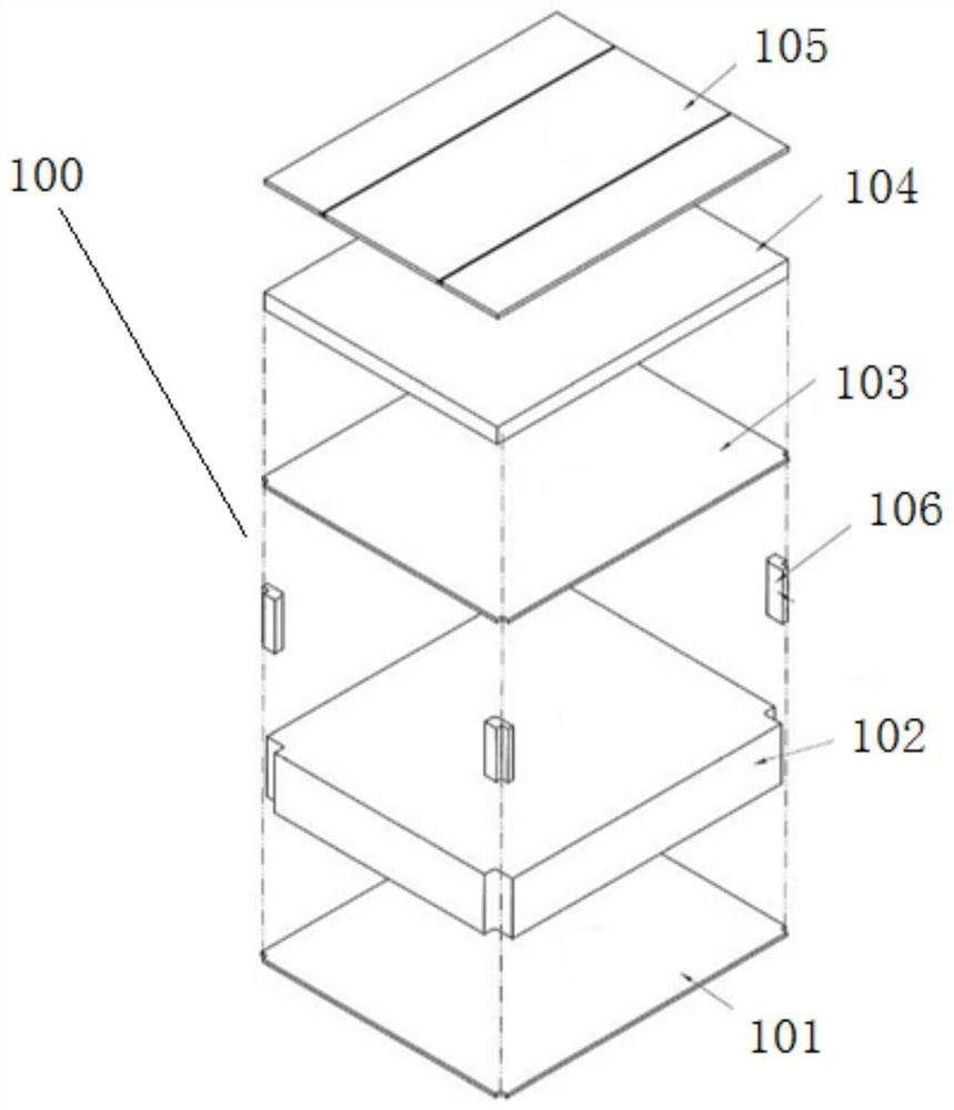
[0056] In order to achieve figure 1 In the illustrated fixing of the insulating box 100 in the curing stage after gluing, this embodiment proposes a corner splint positioning and tensioning device. The insulating box 100 has a five-layer structure, including the second board 102 (ie, the base plate), and the first board 101, the third board 103, the fourth board 104, and the fifth board 105 bonded and compounded on the upper and lower surfaces of the second board 102. Wherein, the four end corners of the No. 2 board 102 are provided with first concave right-angle grooves perpendicular to the upper and lower surfaces, and a corner splint 106 is bonded in the first concave right-angle groove. The outside of the corner splint 106 is connected to the first inner The second concave right-angle groove is parallel to the second concave right-angle groove.

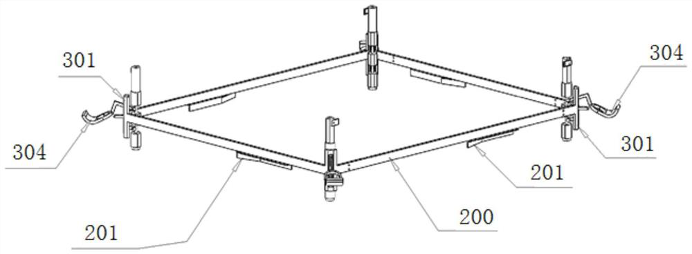
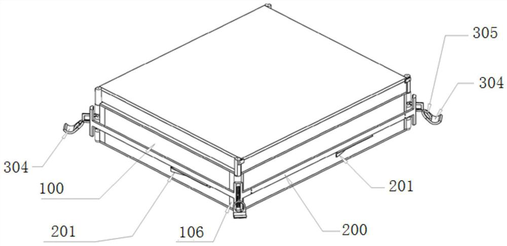
[0057] See figure 2 As shown, the positioning and tensioning device includes an outer frame 200 whose inner size is not less than ...

Embodiment 2

[0067] The difference from Embodiment 1 is that the insulating box 100 targeted by the positioning and tensioning device in this embodiment has only a three-layer structure, that is, it includes the No. 1 board 101, the No. 2 board 102, and the No. 3 board 103. Therefore, correspondingly, the limiting rod 308 above the pressing roller 309 of the positioning and tensioning device in this embodiment is relatively short, and the limiting baffle 310 is not installed.

[0068] In the above embodiments, the surface of the component that is close to or in contact with the adhesive surface of the positioning and tensioning device and the insulating box 100 is made of anti-adhesive material. The anti-adhesive material is preferably polytetrafluoroethylene. The components include a pressing roller 309, a limit bar 308, a limit baffle 310 and so on.


PUM


Abstract

The invention relates to a corner clamping plate locating tensioning device. The corner clamping plate locating tensioning device includes an outer frame with inner side size not less than the side surface contour size of an insulation box and corner frames distributed on the four corners of the outer frame, wherein the corner frames include corner plates fixed to the outer frame, compression rollers located on the inner sides of the corner plates and connecting rod mechanisms connected with the compression rollers and used for driving the compression rollers to compress second concave right-angle grooves. Compared with the prior art, the quality and the efficiency of corner clamping plate assembling can be effectively improved through the corner clamping plate locating tensioning device,installation and disassembling works are more easy and can be operated by one person, furthermore, the corner clamping plate locating tensioning device can be neatly stacked with high density, and fully automated operation and the logistic circulation efficiency are convenient to achieve.

Description

Technical field [0001] The invention belongs to the technical field of the production of insulated boxes of LNG ships, and relates to a corner splint positioning and tensioning device for the production of insulated boxes of LNG ships. Background technique [0002] Part of the box type of LNG ship insulation box adopts a sandwich structure of plywood→polyurethane board→plywood bonded layer by layer, and the four corners need to be bonded with corner plywood. For special working conditions such as sea turbulence and low temperature, this box has strict requirements on bonding strength and assembly accuracy. At present, the assembly of the corner splints at home and abroad is performed manually, and the fixing after glue application is manually fastened with rubber belts and the subsequent time-efficiency planning process is performed. This method has the following problems: 1. The manual tightening method of the rubber band cannot guarantee the uniform force of the corner splint,...

Claims


Application Information

Patent Timeline
Patent Type & Authority Patents(China)
IPC IPC(8): B05D3/00
CPCB05D3/007
Inventor 蒋知峰孔谅周春立冯炜杰王志远梁诚张立中张悦
Owner SHANGHAI JIAO TONG UNIV
Why Eureka
Try Eureka