Electric connector with locking mechanism

A technology for electrical connectors and locking mechanisms, applied in the direction of connections, electrical components, parts of connecting devices, etc., can solve problems such as fork disengagement

Inactive Publication Date: 2004-02-04
JST MFG CO LTD
View PDF2 Cites 7 Cited by
  • Summary
  • Abstract
  • Description
  • Claims
  • Application Information

AI Technical Summary

Problems solved by technology

[0003] However, in an electrical connector with such a locking mechanism, when a certain external force

Method used


Image

  • Electric connector with locking mechanism
  • Electric connector with locking mechanism
  • Electric connector with locking mechanism

Examples


Embodiment Construction

[0017] Hereinafter, preferred embodiments of the present invention will be described with reference to the accompanying drawings.

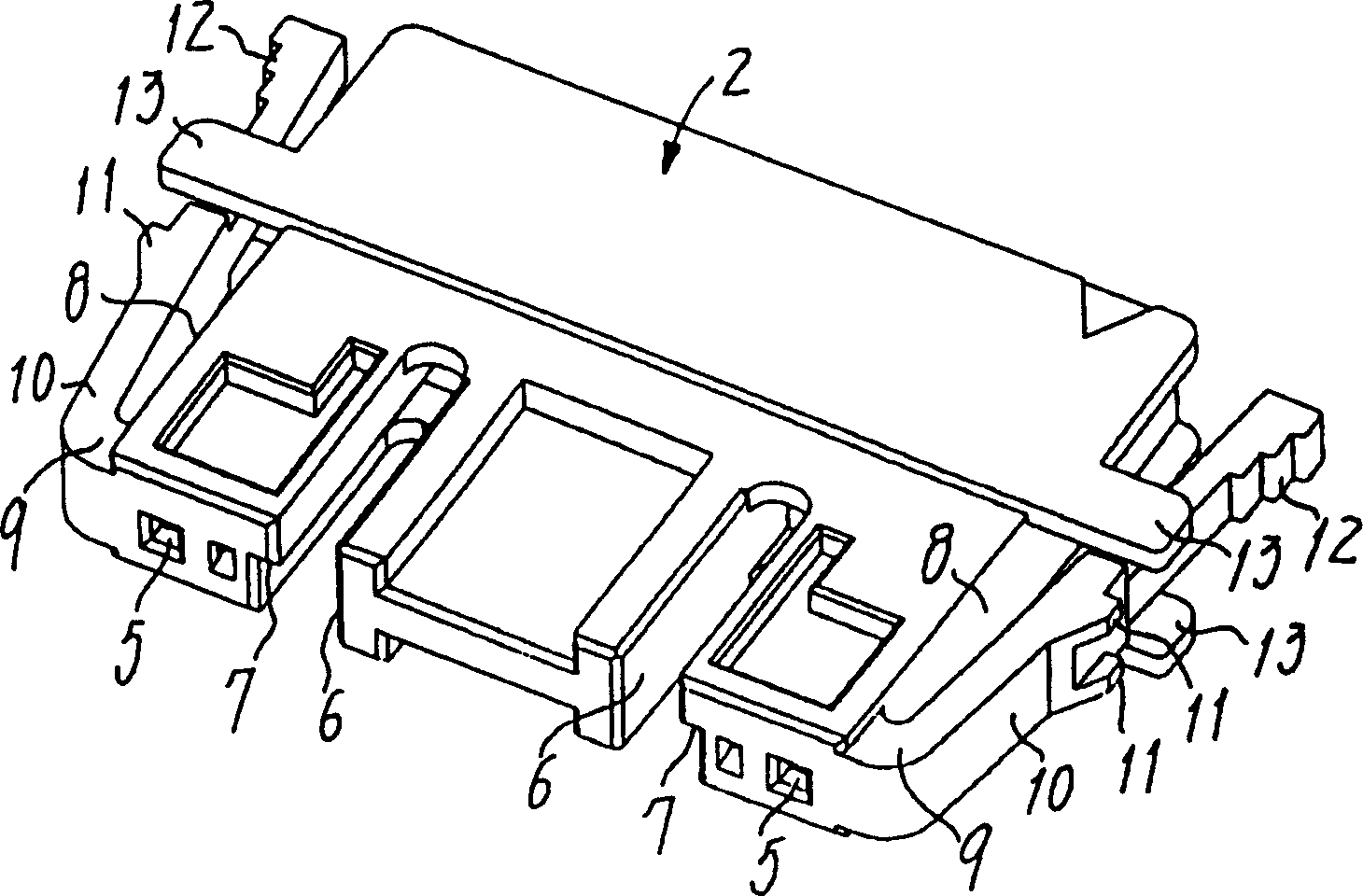
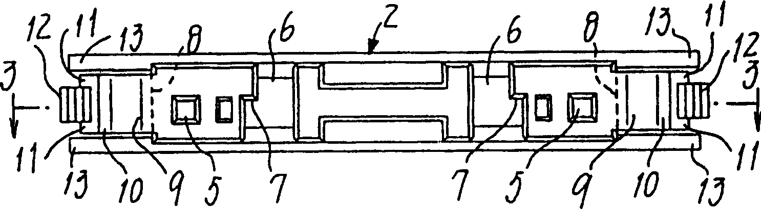
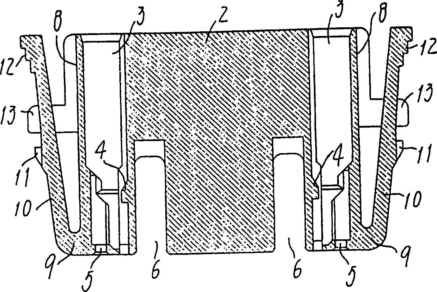
[0018] Figure 1 ~ Figure 3 Represents a socket connector 1 (see Figure 8 and Figure 9 ) of the connector housing, that is, the socket housing 2. This socket housing 2 is made of plastics with insulating properties, and its outline shape is a horizontally long flat rectangular cube, and its two ends are respectively provided with a socket contactor 42 that is connected to the end of the electric wire 41 (see Figure 9 ), the contactor housing chambers 3,3 parallel to each other. This distance between the two contactor accommodation chambers 3, 3 is far away, is a kind of in order to seek to increase the spatial distance between the socket contactor 42, 42 of the connector of high-voltage usefulness and the distance along the surface. The structure of the distance. The inner side wall of each accommodation chamber 3 is provided with a joint ...


PUM


Abstract

The subject of the present invention is: to provide an electrical connector having locking mechanism which can effectively prevent the locking from being released accidentally even if the engagement of the locking arm is released. The solution of the present invention is as follows. An electric connector is constituted from a pair of female/male electric connectors 1 and 21 and a pair of locking arms 10 and 10 which are extended backward from a front edge are integrated to both side surfaces 8 and 8 of one of the connector housings 2 through supporting pieces 9 and 9 which are elastic and deformable. Furthermore, restraining projections 11 and 11 projecting outward are provided in the locking arms 10 and 10. In the other connector housing 22, an empty part 23 is provided to which one of the connector housings 2 and front side parts of both of the locking arms 10 and 10 is engaged and stored. Restraining parts 27 and 27 to which restraining projections 11 and 11 are engaged to are provided to inner walls surfaces 26 and 26 of the empty part 23.

Description

technical field [0001] The present invention relates to a pair of female-convex electrical connectors for embedded connection, in particular, to such an electrical connector having a locking mechanism consisting of the following components: a socket connector having a socket contact for connecting a plurality of electric wires ; Installed on the printed circuit board, the above-mentioned socket connector can be freely connected to it, or a base connector that can be removed from it. Background technique [0002] As a known structure of an electrical connector having such a locking mechanism, for example, it has been disclosed in the following various patent documents: Japanese Patent Document Laid-Open No. 54-14397, US Patent Documents 4,008,941, 4,376,565 specifications and appendices. picture. The structures in these documents are that a lock arm is provided on both sides of one connector housing, and a fork provided on the front end portion of the lock arm and a fork pro...

Claims


Application Information

Patent Timeline
IPC IPC(8): H01R13/639H01R13/62
CPCH01R13/6273H01R13/639
Inventor 黑田桂治新本清
Owner JST MFG CO LTD
Why Eureka
Try Eureka