Oil Controller for two-stroke engine

A technology for engines and internal combustion engines, applied to combustion engines, internal combustion piston engines, and controlling the pressure of lubricants, etc., which can solve problems such as the complexity of the control system, the increase in the number of components, and the placement of throttle valve position sensors.

Inactive Publication Date: 2004-02-11
MORIC CO LTD
View PDF2 Cites 6 Cited by
  • Summary
  • Abstract
  • Description
  • Claims
  • Application Information

AI Technical Summary

Problems solved by technology

[0006] The orifice sensor is used in the conventional lubricant control system to detect the orifice opening, the application of the orifice sensor will lead to an increase in the number of components and the complexity of the control system
This will obviously increase the cost of the vehicle
In addition, especially in small vehicles there can be problems with the placement of various components, especially the placement of the throttle position sensor due to the limited space around the engine

Method used


Image

  • Oil Controller for two-stroke engine
  • Oil Controller for two-stroke engine
  • Oil Controller for two-stroke engine

Examples


Embodiment Construction

[0016] Before describing the invention with reference to the accompanying drawings, the contents of the above-mentioned co-pending application are hereby incorporated by reference as there is shown in more detail the basic type of engine with which the invention can be utilized and a basic Spark time control apparatus and method. However, it is also believed that from the following description, those skilled in the art will not only understand how to practice the present invention with the basic structure and method shown in this application, but also understand how to use the engine lubrication system to be described hereinafter. practice the invention.

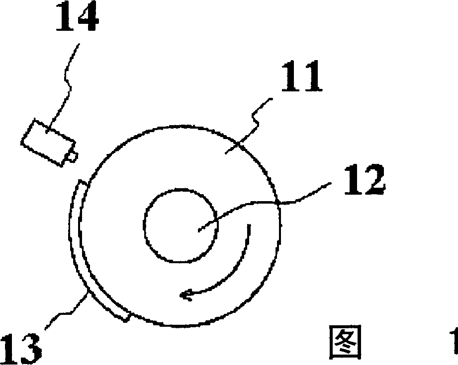
[0017] Referring next in detail to the drawings, and first to Figure 1, there is shown an engine timing sensor, for example, associated with an engine driven shaft member of any desired type of associated internal combustion engine. In particular, a flywheel 11 is fixed for rotation with the engine shaft, in particular the ...


PUM


Abstract

A method and apparatus that permits engine system control such as exhaust valve timing without the use of separate load sensors from the output of a single engine timing sensor.

Description

[0001] References to related applications [0002] This application is pending application serial number 09 / 682457, filed September 5, 2001, and entitled "Engine Control Method and Apparatus" in our and another inventor's name Continuing application in part of the above-mentioned pending application is assigned to the assignee herein. technical field [0003] The present invention relates to an engine control system for controlling an engine lubrication system, and more particularly to a lubrication system of a two-cycle engine. Background technique [0004] The aforementioned pending application discloses a very simple yet extremely effective way of determining engine load and controlling the engine ignition system in response to the determined load, thereby simplifying engine operation. Due to the simplicity of the method and device, the method and device allow for application to relatively small, low production volume engines, such as motorcycles, scooters and the like. ...

Claims


Application Information

Patent Timeline
IPC IPC(8): F01M1/16
CPCY02T10/18Y02T10/46
Inventor 矶田直也长津善之
Owner MORIC CO LTD
Why Eureka
Try Eureka