Foot-propelled drive with central power-transportation and control automatic overshoes machine

A shoe cover machine and power transmission technology, which is applied in applications, clothing, hangers, etc., can solve problems such as unstable output properties, blocked pedal force transmission, and force obstruction, and achieve the effect of improving stability and reliability

A shoe cover machine and power transmission technology, which is applied in applications, clothing, hangers, etc., can solve problems such as unstable output properties, blocked pedal force transmission, and force obstruction, and achieve the effect of improving stability and reliability

CN1481749AInactive Publication Date: 2004-03-17CHINA JILIANG UNIV

Image

  • Foot-propelled drive with central power-transportation and control automatic overshoes machine
  • Foot-propelled drive with central power-transportation and control automatic overshoes machine

Examples


Embodiment Construction

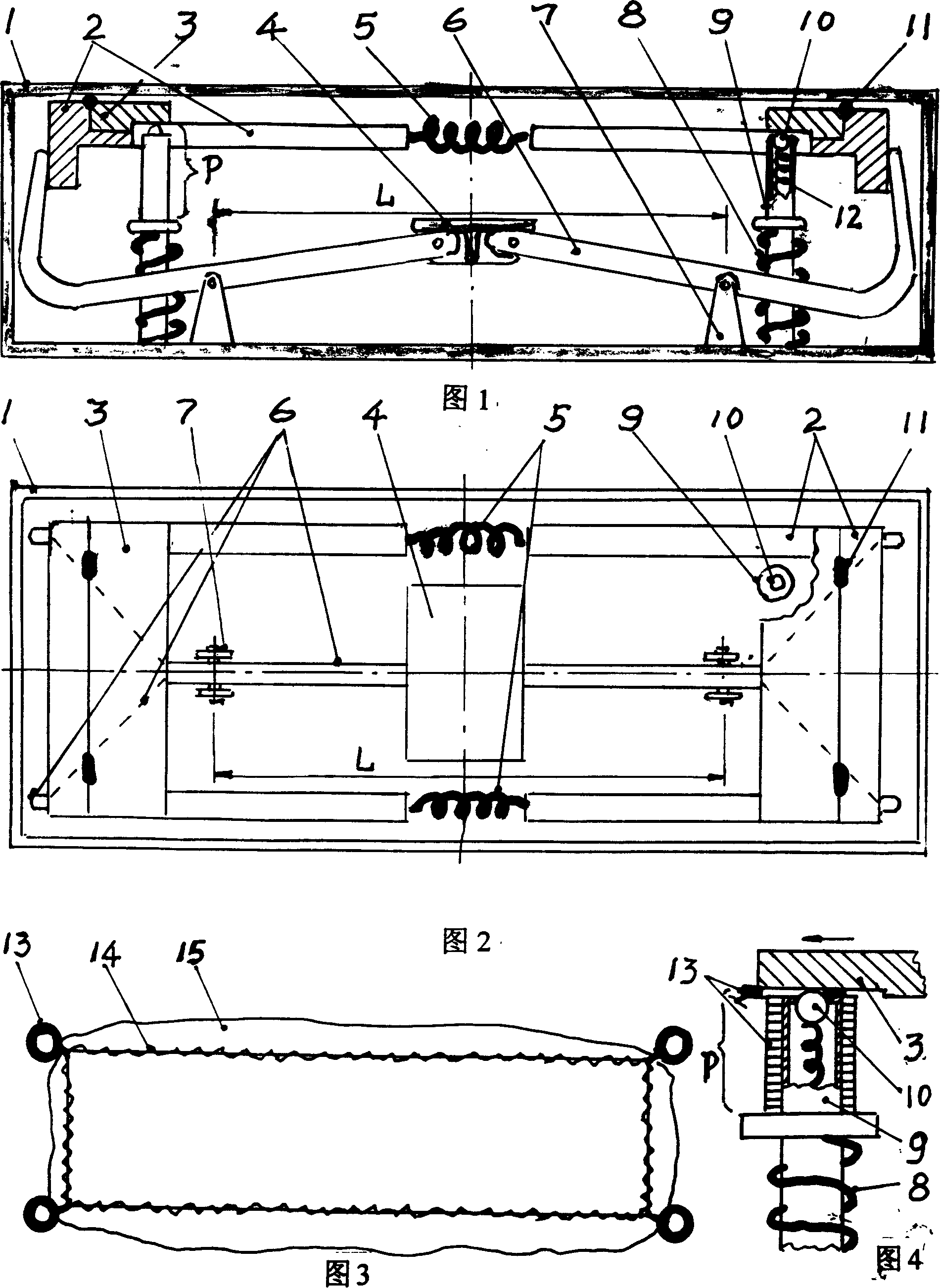
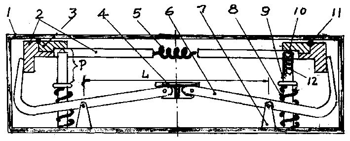
[0018] The vertical arrow in Fig. 1 indicates the direction of the pedal, when the pedal pressure on the pedal (4) passes through the single power transmission rod (6) on the center line, and the bifurcated parts of the upper hook at both ends When driving the left and right slide blocks (2) to operate relatively, as shown in Figure 4, the shoe cover ring removal block (3) on the left and right slide blocks (2) passes through the trapezoidal lower convex surface of its lower side, Promote the shoe cover rings (13) that are temporarily positioned on the four corners and wait to be dismounted at any time to make it overcome the elastic resistance formed by the marbles (10) supported by the pin clip springs (12) on the respective positions, from the four shoe covers Squeeze and take off on the positioning post (9), at last, allow elastic shoe collar (14) to be enclosed within the people's pin foot bowl position on the pedal (4) with flexible shoe cover (15) automatically.

[0019...


PUM


Abstract

The automatic foot driven and controlled shoe sheath machine with central force application is one improvement of available machine with treading force applied in two sides, and has central single-sided force application mode, rather than two-side force application mode. The present invention makes the treading force reach the destination smoothly, has raised operation stability and reliability, simplified structure and convenient installation and regulation. It is suitable for household, hotel shop and lab with high requirement in cleanness.

Description

Technical field: [0001] The invention relates to a dynamic mechanical structure engineering technology serving shoe cover machinery. Background technique: [0002] At present, in many occasions, such as: residential buildings with floors laid, laboratories and workshops with special requirements for cleanliness, before entering, you have to take off your dirty shoes and put on clean special shoes, or do not take off your shoes. After taking off the dirty shoes, put clean shoe covers directly on the dirty shoes by yourself. Although the latter action and process are simple, it cannot be said to be a very pleasant thing that does not feel cumbersome. Therefore, many people have been exploring how to design a practical automatic shoe cover machine to solve the above-mentioned problems conveniently and quickly. [0003] Yet, the scheme that proposes for this shoe cover machine is a lot, and wherein also has made prototype. But still do not have a kind of practical automatic s...

Claims


Application Information

Patent Timeline
17 Mar 2004
Publication
CN1481749A
IPC
A47G25/80
Inventors
梁嘉麟