Temperature sensor and method of producing the temperature sensor

a temperature sensor and temperature sensor technology, applied in the direction of positive temperature coefficient thermistors, instruments, heat measurement, etc., can solve the problems of temperature sensitive element electrodes escaping damage, temperature sensitive element electrodes escaping breaking, etc., to enhance the stable characteristic enhance the stability of the temperature sensitive element, and improve the effect of gas permeability

Active Publication Date: 2008-08-28
DENSO CORP
View PDF9 Cites 44 Cited by
  • Summary
  • Abstract
  • Description
  • Claims
  • Application Information

AI Technical Summary

Benefits of technology

[0033]Specifically, the thermistor body of the thermistor element is covered with the anti-vibration filler in order to avoid breaking of the electrodes caused by vibration. This configuration avoids the wires of the electrodes of the thermistor element from breaking. In addition, it is possible to keep the anti-vibration function at the connection node between the metal core wires and the lead wires while keeping the electrical insulation between those wires.
[0034]In the temperature sensor as another aspect of the present invention, the thermistor element is mainly of an oxide semiconductor. Specifically, the thermistor element is made of an oxide semiconductor or a material composed of an oxide semiconductor. Although the oxide semiconductor generally changes its temperature-resistance characteristic based on the partial pressure of oxygen contained in an ambient atmospheric gas, the configuration of the temperature sensor according to the present invention having a superior gas permeability to supply oxygen into the thermistor element can provide the stable characteristics of the oxide semiconductor forming the thermistor element.
[0035]In the temperature sensor as another aspect of the present inventio...

Problems solved by technology

As a result, the temperature sensitive element in the temperature sensor having the above config...

Method used


Image

  • Temperature sensor and method of producing the temperature sensor
  • Temperature sensor and method of producing the temperature sensor
  • Temperature sensor and method of producing the temperature sensor

Examples


first embodiment

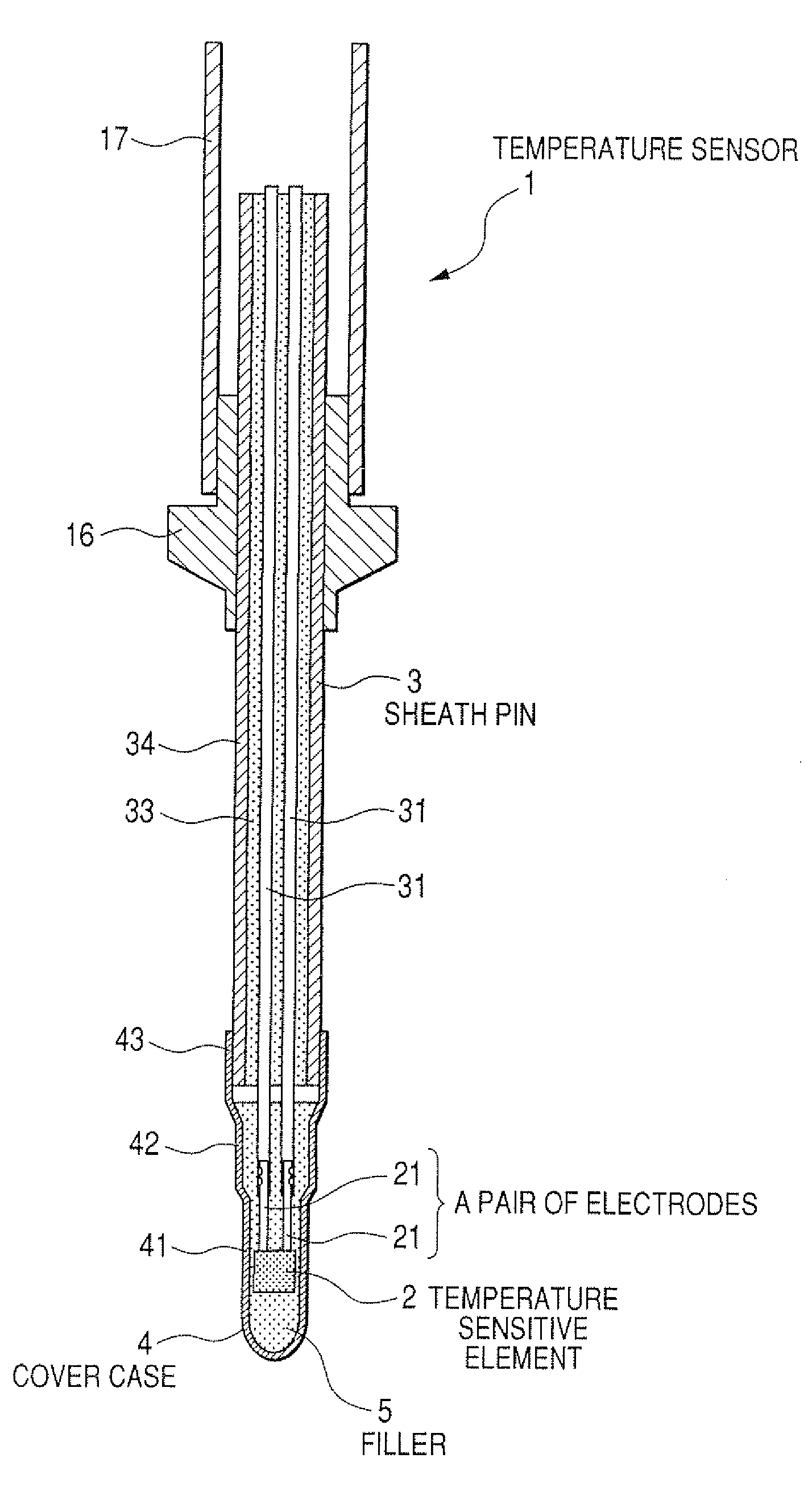
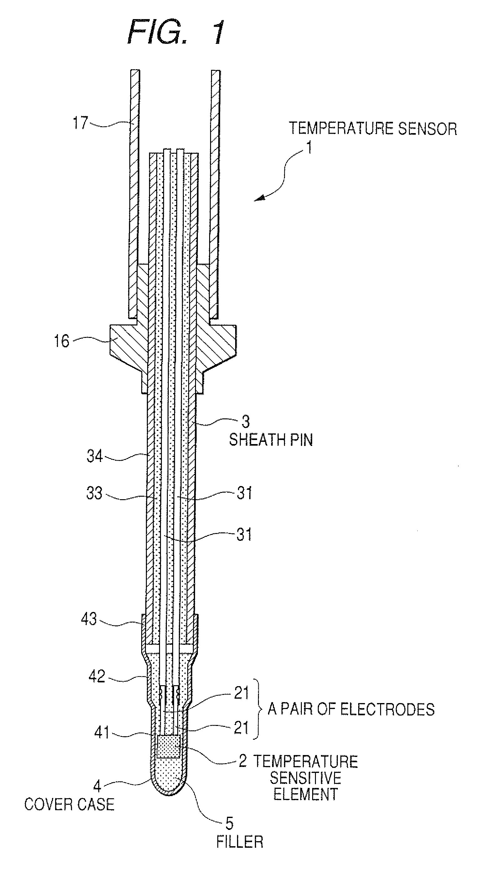
[0069]A description will be given of a temperature sensor and a method of producing the temperature sensor according to a first embodiment of the present invention with reference to FIG. 1 to FIG. 4.

[0070]FIG. 1 is a longitudinal cross section of the temperature sensor 1 according to the first embodiment of the present invention.

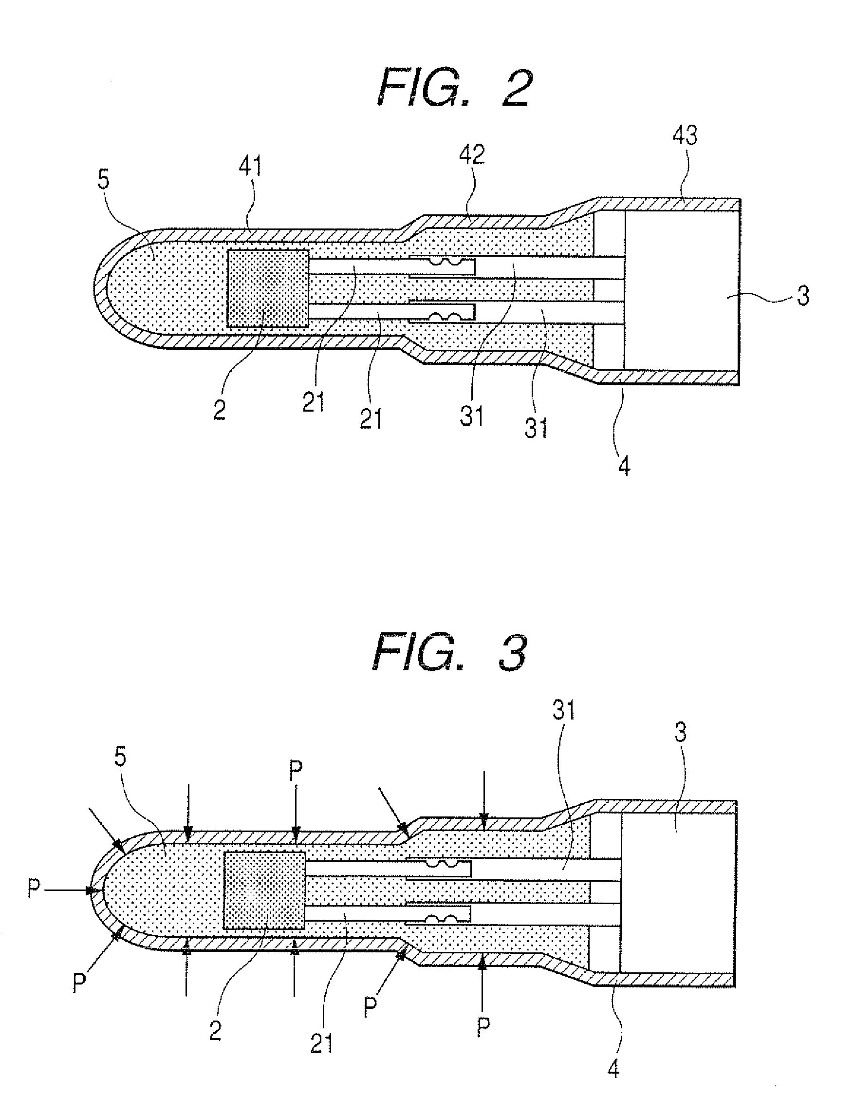
[0071]As shown in FIG. 1, the temperature sensor 1 of the first embodiment is comprised of a temperature sensitive element 2, a sheath pin 3, and a front cover case 4 (hereinafter, referred to as the “cover case 4”). The sheath pin 3 has a pair of built-in signal wires 31 connected to a pair of electrodes 21 of the temperature sensitive element 2. The cover case 4 is placed at the front of the temperature sensitive element 2. The temperature sensitive element 2 is covered with the cover case 4. The temperature sensitive element 2 changes its electrical characteristic based on the ambient temperature. A front part of the built-in signal wires 31 in the sheath...

second embodiment

[0106]A description will be given of a temperature sensor and a method of producing the temperature sensor according to a second embodiment of the present invention with reference to FIG. 7 to FIG. 9.

[0107]The second embodiment of the present invention provides a preferable filler raw material to be used in producing the temperature sensor according to the present invention The preferable filler raw material is a thermal resistance ceramic material composed mainly of one of alumina (Al2O3), silicon dioxide (SiO2), magnesium oxide (MgO), and zirconium dioxide (ZrO2). It is preferable to use a material as the main component of the filler 5 which has a similar thermal expansion coefficient to the temperature sensitive element 2, and also has a superior thermal conductivity. The following Table 1 shows the thermal expansion coefficient and the thermal conductivity of each raw material. The thermal expansion coefficient of the thermistor is 8×10⁻⁶ / ° C.

TABLE 1PhysicalMain componentprope...

third embodiment

[0122]A description will be given of a temperature sensor and a method of producing the temperature sensor according to a third embodiment of the present invention with reference to FIG. 10 to FIG. 12.

[0123]In the third embodiment, the small diameter part 41 in the cover case 4 where the filler has been filled was vertically cut into a plurality of parts. A plurality of the parts were used as experimental samples in the third embodiment. In particular, the cover case for use in the experiment according to the third embodiment has no temperature sensitive element therein.

[0124]The outer diameter of the small diameter part 41 of the cover case 4 was 2.5 mm, and the inner diameter thereof was 1.88 mm. The filler 5 was obtained by the composition ratio shown in the second embodiment. That is, the average particle size of alumina was within a range of 1 to 4 μm, and the amount of water was within a range of 15 to 25 wt %.

[0125]FIG. 10 is an explanatory diagram showing the small diameter ...


PUM

PropertyMeasurementUnit
Temperatureaaaaaaaaaa
Fractionaaaaaaaaaa

Abstract

In a temperature sensor having a temperature sensitive element, a sheath pin connected to the temperature sensitive element, and a cover case. The cover case, filled with a filler, accommodates the temperature sensitive element and the sheath pin. A hardening temperature of the filler is not less than an actual usage environment of the temperature sensor. Another temperature sensor has a temperature sensitive element exposed at a high temperature of not less than 750° C., a thermistor element, a sheath pin, an anti-vibration filler, and a metal cover case fixed to an end part of the sheath pin. The metal cover case accommodates the sheath pin and the thermistor element. The filler is made of a porous insulation material having a pore ratio within a range of 30 to 70% and filled around the thermistor element in the metal cover case.

Description

CROSS-REFERENCE TO RELATED APPLICATION[0001]This application is related to and claims priority from Japanese Patent Applications No. 2007-46769 filed on Feb. 27, 2007 and No. 2007-51215 filed on Mar. 1, 2007, the contents of which are hereby incorporated by reference.BACKGROUND OF THE INVENTION[0002]1. Field of the Invention[0003]The present invention relates to a temperature sensor and a method of producing the temperature sensor, which is installed in an exhaust gas system, capable of detecting the temperature of the exhaust gas in an exhaust gas pipe emitted from for an internal combustion engine.[0004]2. Description of the Related Art[0005]There is known a temperature sensor installed in the exhaust gas pipe in the exhaust gas system for an internal combustion engine. Such temperature sensor is equipped with a temperature sensitive element. The temperature sensitive element is capable of changing its electrical characteristics according to the magnitude of the ambient temperatur...

Claims


Application Information

Patent Timeline
IPC IPC(8): G01K7/16G01K1/08
CPCG01K1/08G01K1/12Y10T29/49117G01K13/02G01K2205/04G01K7/22
Inventor TOUDOU, YUUSUKEKUZUOKA, KAORU
Owner DENSO CORP
Why Eureka
Try Eureka