
Method for drying articles used in dust-free room

A drying treatment, clean room technology, applied in the direction of drying solid materials, heating to dry solid materials, drying, etc., can solve the problems of no benefit, long time, energy waste, etc., and achieve highly creative effects

Inactive Publication Date: 2004-03-24
台卫科技股份有限公司
View PDF0 Cites 2 Cited by
  • Summary
  • Abstract
  • Description
  • Claims
  • Application Information

AI Technical Summary

Problems solved by technology

However, it not only takes a long time to completely dry the wet dust-free clothes, but also needs to extract a large amount of dry air from the outside to achieve the purpose of drying.
As a result, a large amount of energy is wasted, and there is no benefit at all

Method used


Image

  • Method for drying articles used in dust-free room
  • Method for drying articles used in dust-free room
  • Method for drying articles used in dust-free room

Examples


Embodiment Construction

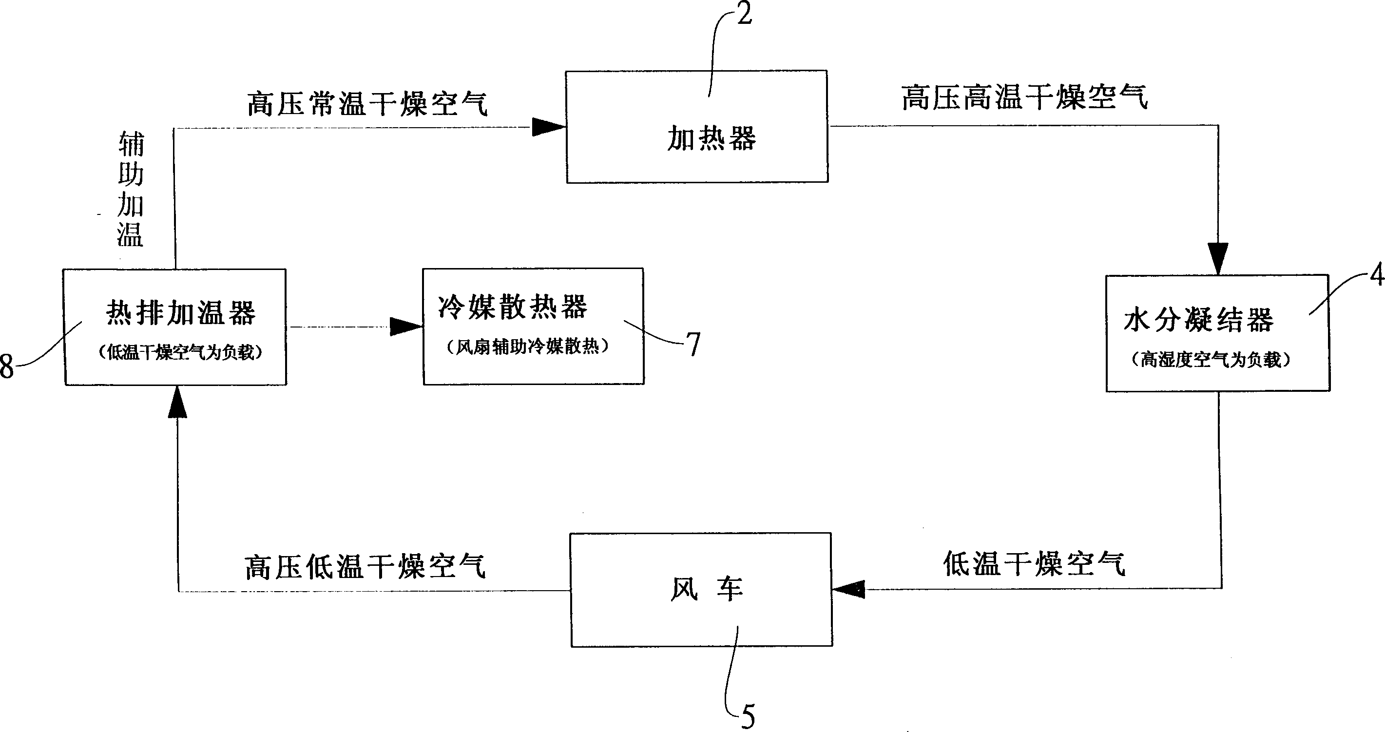
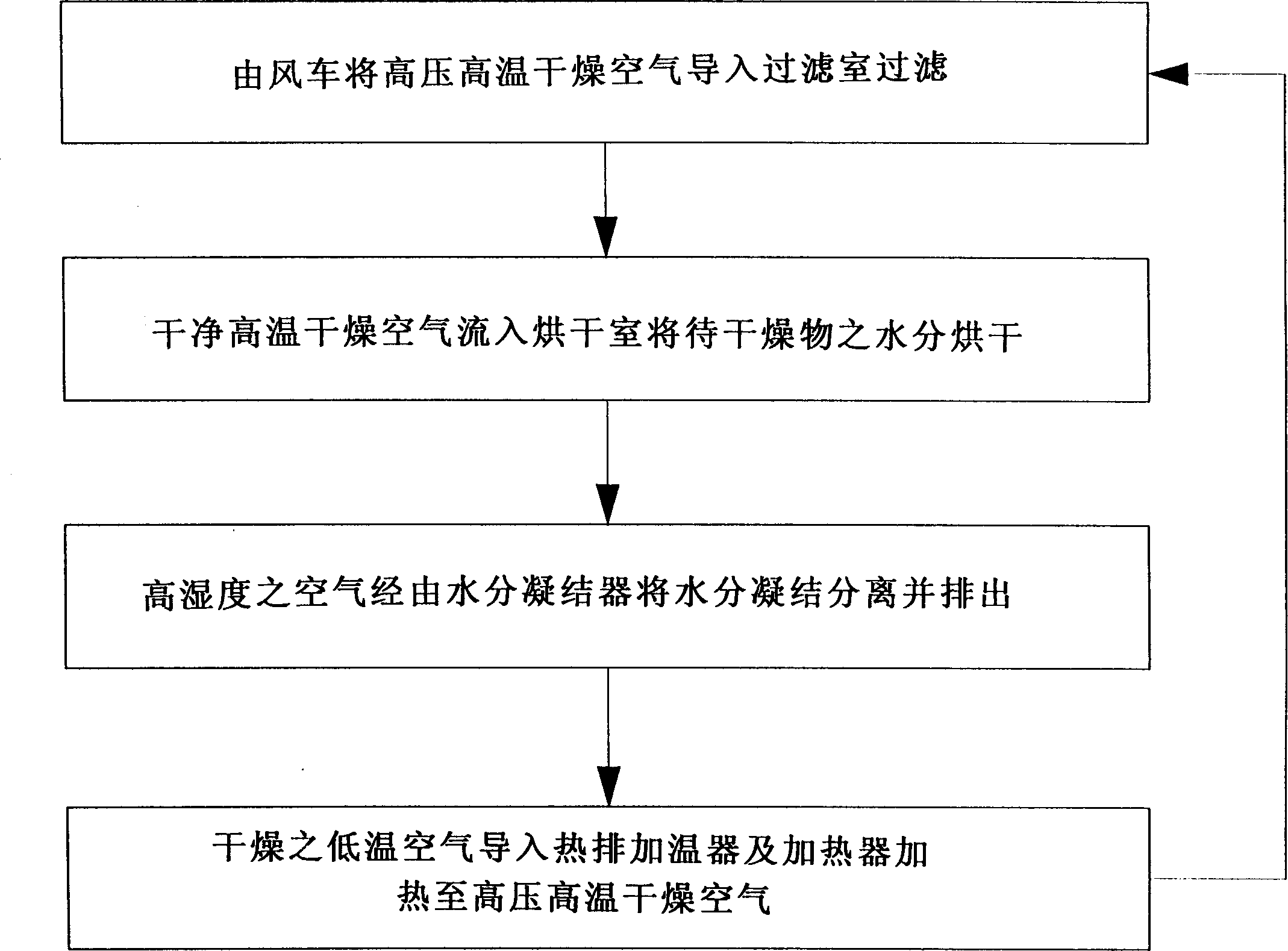
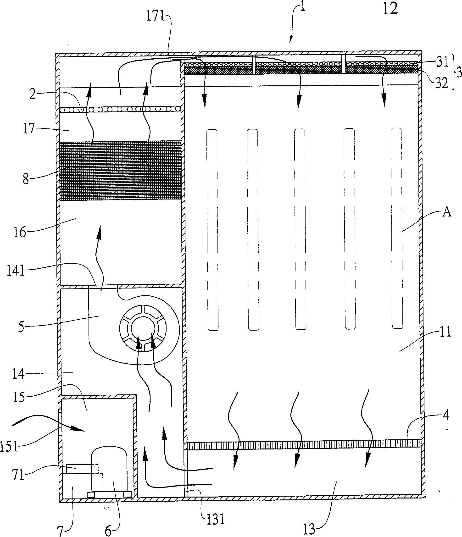
[0028] Drying treatment method of the present invention (please refer to figure 1 , 2 , 3), including the functional interaction of components such as the main body 1, the heater 2, the filter device 3, the moisture condenser 4, the windmill 5, the compressor 6, the refrigerant radiator 7 and the heat row heater 8; wherein :

[0029] The main body 1 is mainly provided with an airtight drying chamber 11 on one side thereof for accommodating objects to be dried A (clean clothes in the specific embodiment of the present invention), and above and below the drying chamber 11 respectively Establish a filter chamber 12 and an L-shaped passage 13, and this passage 13 communicates with the windmill chamber 14 next to the drying chamber 11, and forms an air outlet 131 between the two, and, on the top wall of the windmill chamber 14, A through hole 141 is provided, and an isolation chamber 15 is arranged on the side adjacent to the channel 13 below it, and an air hole 151 is provided o...


PUM


Abstract

The present invention relates to a drying treatment method of dustless chamber article, and is characterized by that it utilizes high-temp. dried air and makes it be continuously circularly flowed in a closed space to quickly dry the water content on the article to be dried, and can introduce the wet air produced by drying article into the moisture coagulator to separate out the water content from air, then further reverse the dried air and reuse it by heating, so that said operation can be adopted repeatedly so as to attain the goal of quickly drying article.

Description

technical field [0001] The invention relates to a drying treatment method, in particular to a drying treatment method for articles used in a clean room. Background technique [0002] In the past, it was generally used to dry some special items, especially the special clean clothes in the clean room, because it is strictly forbidden to dry them outdoors or air dry after cleaning. Therefore, in the past, when cleaning the dust-free clothes, they were usually air-dried in a clean room. However, it not only needs quite a long time when desiring to completely air-dry its wet dust-free clothes, but also needs to extract a large amount of dry air from the outside to achieve the purpose of drying. But cause the waste of a large amount of energy like this, do not have any benefit at all. In view of the various defects and inconveniences caused by the above-mentioned old methods, the inventor believes that it is necessary to make corrections urgently, so with his many years of exper...

Claims


Application Information

Patent Timeline
Patent Type & Authority Applications(China)
IPC IPC(8): F26B3/06
Inventor 曾仁慈蔡鸿明
Owner 台卫科技股份有限公司
Learn More