Connector crossing shielding housing structure

A connector and pass-through technology, which is applied to the protective grounding/shielding device of the connecting parts, the parts of the connecting device, and the connection direction, which can solve the problems of insufficient stability of the fixing method, many components, and restrictions on the selection and use.

Inactive Publication Date: 2016-10-05
KUANG YING COMPUTER EQUIP CO LTD
View PDF5 Cites 1 Cited by
  • Summary
  • Abstract
  • Description
  • Claims
  • Application Information

AI Technical Summary

Problems solved by technology

[0004] 1. The accommodating space of the metal shell is fixed, and it can only accommodate cables with a single wire diameter. The selection and use of wires with different wire diameters is limited.
[0005] 2. The general metal shell is not integrally formed, there are many parts and components, and the assembly action is more complicated
[0006] 3. On the bearing, the wire or circuit board may be damaged during the assembly process
[0007] 4. The fixing method between the metal shell and the connector body is not stable enough

Method used


Image

  • Connector crossing shielding housing structure
  • Connector crossing shielding housing structure
  • Connector crossing shielding housing structure

Examples


Embodiment Construction

[0053] In order to achieve the above-mentioned purpose and effect, the technical means and the structure adopted by the present invention are hereby described in detail with respect to the preferred embodiments of the present invention.

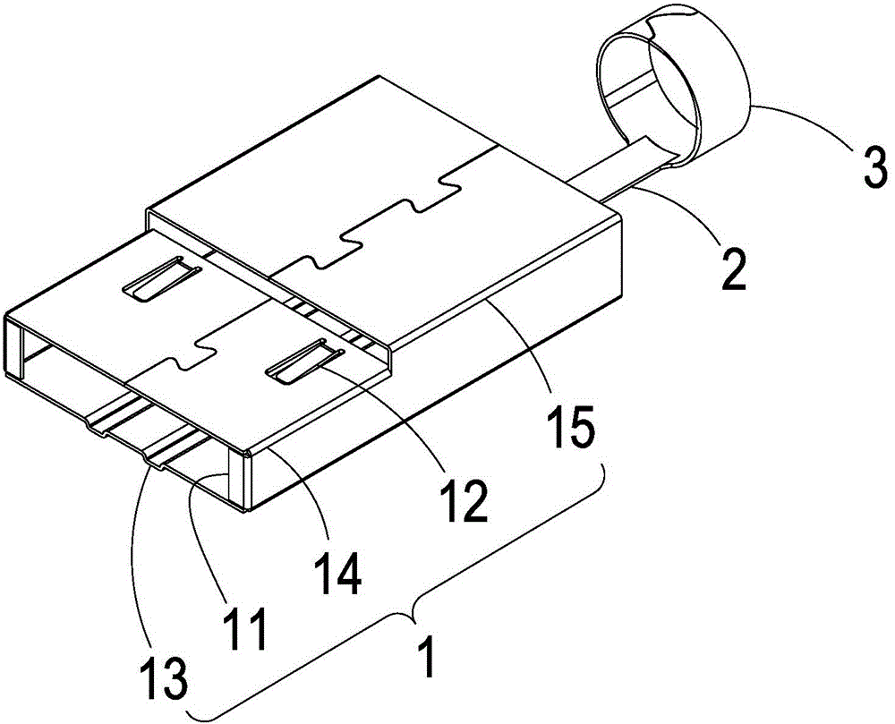
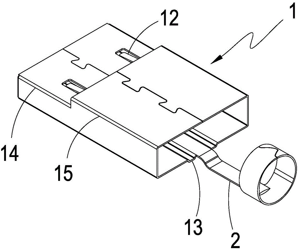
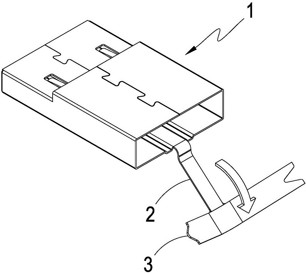
[0054] see figure 1 , figure 2 , image 3 and Figure 4 As shown, it is a perspective view of a preferred embodiment of the present invention, a perspective view of another angle, a schematic view of the action (1) and a schematic view of the action (2). It can be clearly seen from the figure that the present invention includes:

[0055] A shielding shell 1 for sheathing a connector male head 4, the shielding shell 1 defines a positioning part 14 for increasing structural stress, and a limit position that is higher than the positioning part 14 and can be limited inwardly part 15, and the front side of the shielding shell 1 has at least one front baffle 11 for limiting the connector male head 4, and the shielding shell 1 side has at least ...


PUM


Abstract

The present invention provides a connector crossing shielding housing structure. The main structure comprises a shielding housing sleeved with a connector male head, a flexible connection piece formed by extending the rear end of the shielding housing and a flexible ring sleeving piece formed at one end, far away from shielding housing, of the flexible connection piece and configured to fix wire rods. Through the structure, a user bends the flexible connection piece downwards to vacate the space at the rear end of the shielding housing so as to allow the connector male head to smoothly sleeve the shielding housing, expand the flexible ring sleeving piece and allow the wire rods of the connector male head to be arranged on the flexible ring sleeving piece to fold the expanding flexible ring sleeving piece for encircling the wire rods. Therefore, a male head iron housing having a sleeving end terminal and with simple structure and easy installation is formed.

Description

technical field [0001] The present invention provides a structure of a connector pass-through shielding case, especially a structure of a connector pass-through shielding case with a simple structure and convenient installation. Background technique [0002] By the way, the wire-end connector mainly includes a transmission body, a metal shell and insulating colloid that cover the outside of the transmission body in sequence. Among them, the transmission body has a plastic frame and a plurality of terminals inserted in the plastic frame, and each terminal is welded to each discrete core wire of the cable; the metal shell has the function of an electric screen, so that the electromagnetic wave of the signal transmitted by the transmission body does not Mutual interference with external electromagnetic waves; the top surface of the insulating colloid has a single fulcrum buckle, which is used to buckle with the buckle hole set at the corresponding position of the board end conn...

Claims


Application Information

Patent Timeline
IPC IPC(8): H01R13/516H01R13/502H01R13/648
Inventor 钟轩禾林昱宏
Owner KUANG YING COMPUTER EQUIP CO LTD
Why Eureka
Try Eureka