
Chord axis apparatus for stringed instrument and its manufacture method

A technology for stringed instruments and pegs, which is applied in the field of peg devices and its manufacture, can solve the problems of increasing the number of complex parts and high manufacturing costs, and achieve the effect of eliminating shaking and stable quality

Inactive Publication Date: 2004-03-31
GOTOH GUT
View PDF0 Cites 7 Cited by
  • Summary
  • Abstract
  • Description
  • Claims
  • Application Information

AI Technical Summary

Problems solved by technology

But, in this peg device, there is the problem of increasing the number of complex components, and the manufacturing cost is high.

Method used


Image

  • Chord axis apparatus for stringed instrument and its manufacture method
  • Chord axis apparatus for stringed instrument and its manufacture method
  • Chord axis apparatus for stringed instrument and its manufacture method

Examples


Embodiment Construction

[0034] Below, refer to Figure 1 to Figure 6 Embodiments of the present invention will be described.

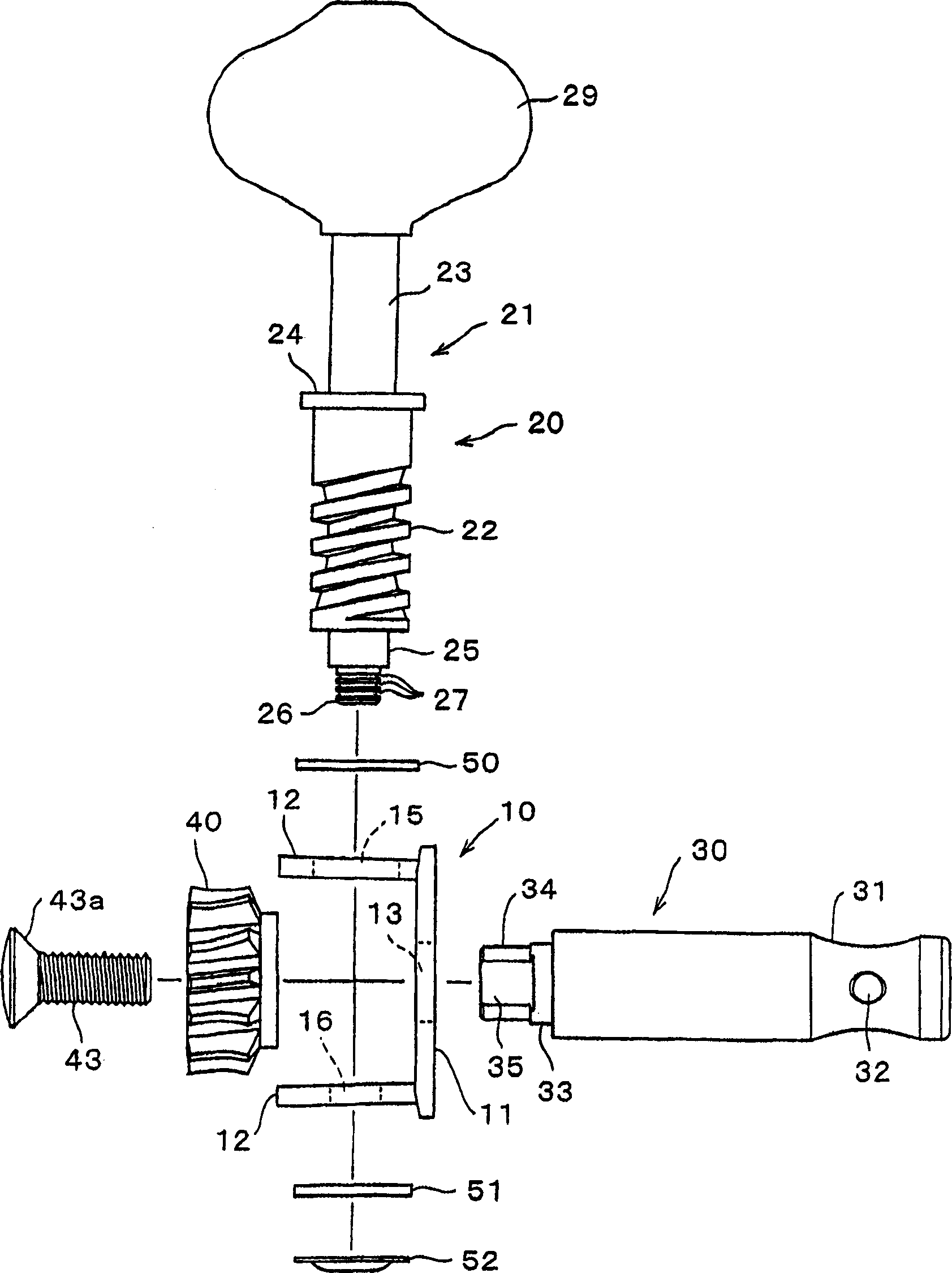
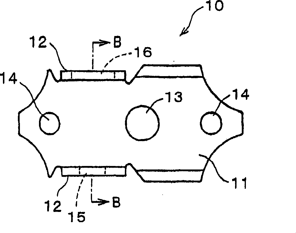
[0035] figure 1 It is an assembly plan view of the peg device of the embodiment. In the figure, numeral 10 is a main body, 20 is a worm gear assembly, 30 is a reel, and 40 is a worm gear. Hereinafter, these structures will be described in order, figure 2 is a plan view showing the main body 10 . As shown in the figure, the main body 10 has a substantially rectangular shape in plan view, and is composed of a flat base 11 and bearings 12 erected from both sides of the base 11 . In the base portion 11, a support hole 13 for freely rotatably supporting the reel 30 is formed. In addition, holes 14 for attaching the peg unit to the head of the classical guitar with screws are formed in the base portion 11 .

[0036] A large diameter hole 15 for freely rotatably supporting the base of the worm gear shaft assembly 20 is formed in one bearing 12, and a small diameter hole for ...


PUM


Abstract

A stringed instrument string winder, comprising a main body (10), bearings (12) rising from both sides of the main body (10) and opposed to each other, a worm gear (21) supported rotatably on a largediameter hole (15) and a small diameter hole (16) of the bearings(12) and having a peg (29) at one end part thereof, and a windup shaft (30) connected to the worm gear (21) through a worm wheel (40),wherein the bearings (12) are made of a spring material, whereby an elastic limit of the bearings is increased to prevent a deformation from occurring.

Description

technical field [0001] The invention relates to a peg device of a stringed instrument such as a guitar and a manufacturing method thereof, in particular to a technology for reducing the backlash between gears by preventing wobble between the worm gear device and the bearing. Background technique [0002] Figure 9 It is a diagram showing an example of a peg device for a classical guitar in the prior art. The structure of the peg device shown in this figure is that a worm gear rod 3 with a knob 2 fixed at one end is freely rotatably supported on the main body 1 mounted on the guitar head, and the worm gear 4 engaged with the worm gear rod 3 can be rotated freely. While being freely rotatably supported by the main body 1, a spool 5 whose axis line coincides with the worm wheel 4 is attached to the worm wheel 4 with screws 6. [0003] Here, on the main body 1, there are formed a plurality of pairs of bearings 7 that are formed by press-forming a common steel plate and are rais...

Claims


Application Information

Patent Timeline
Patent Type & Authority Applications(China)
IPC IPC(8): G10D3/14
CPCG10D3/14
Inventor 后藤孝夫
Owner GOTOH GUT
Learn More