Drum convex lug fixing structure

A technology for fixing structures and lugs, applied to percussion instruments, instruments, musical instruments, etc., can solve problems such as hindering the replacement of the drum head 2, and difficult bolts for the operator, and achieve the effect of preventing falling off

Inactive Publication Date: 2004-04-14
YAMAHA CORP
View PDF1 Cites 2 Cited by
  • Summary
  • Abstract
  • Description
  • Claims
  • Application Information

AI Technical Summary

Problems solved by technology

However, it is difficult for the operator to temporarily hold all the bolts 9, which are arranged at equal intervals on the outer circumference of the hollow cylinder 1
Similar to the above lug fixing structure of Figures 9 and 10, the attached Figure 11 A further improvement in the lug fixing structure of ® also shows that there is a space, because it still hinders the replacement of the drumhead 2

Method used


Image

  • Drum convex lug fixing structure
  • Drum convex lug fixing structure
  • Drum convex lug fixing structure

Examples


Embodiment Construction

[0038] The present invention will be described in further detail below by way of example with reference to the accompanying drawings.

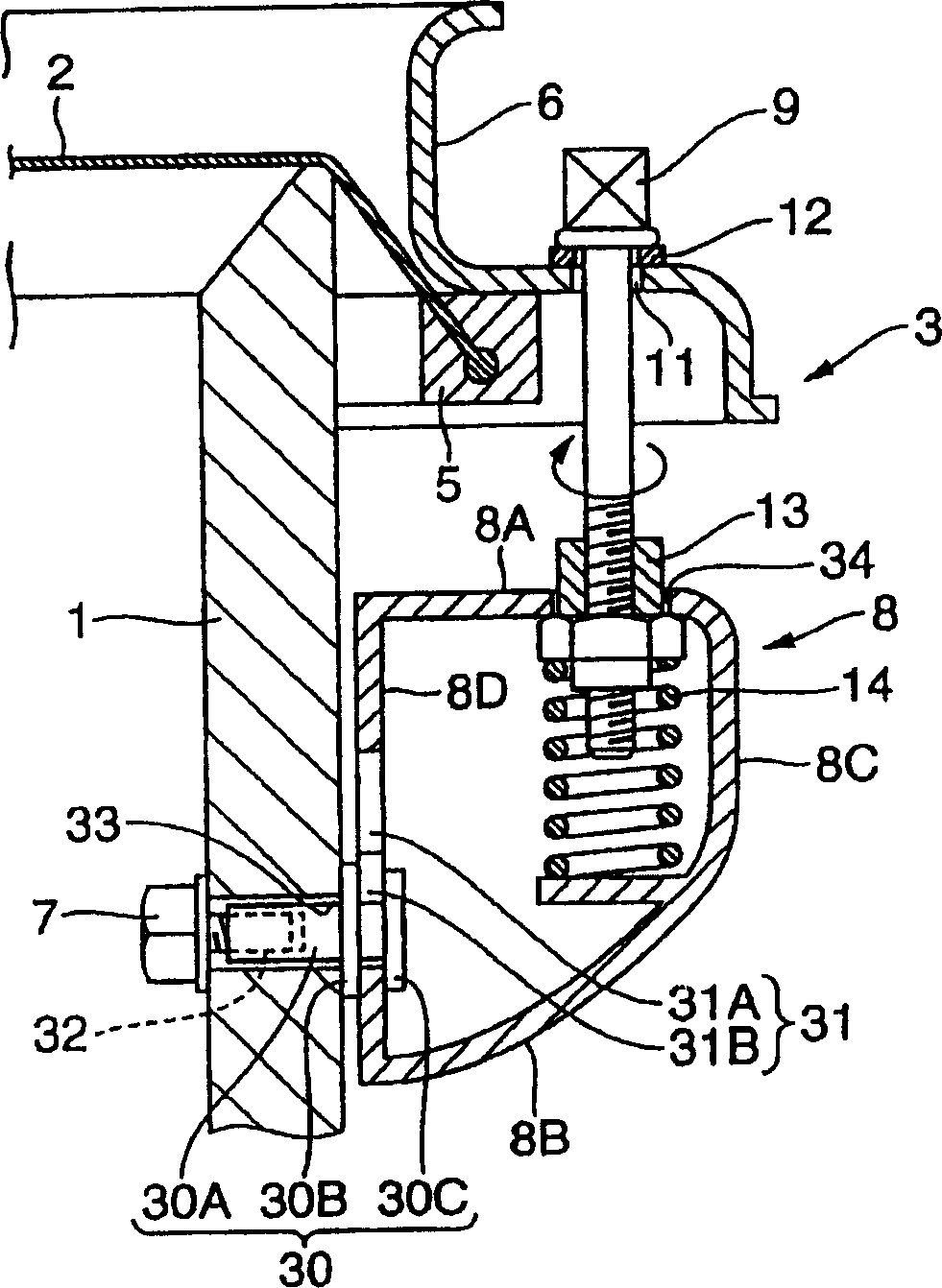
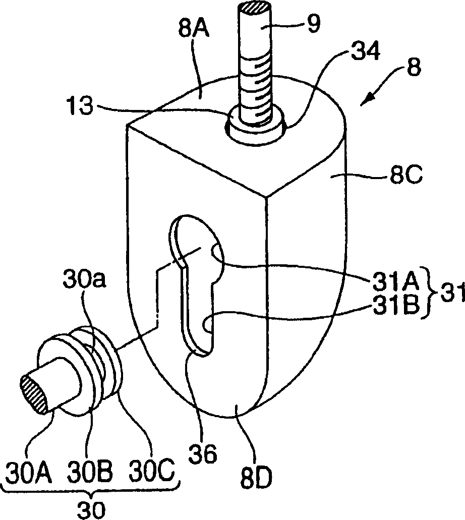
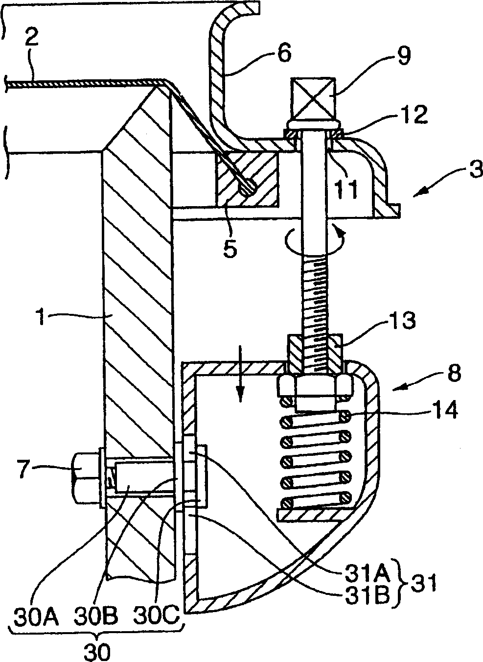
[0039] figure 1 is a sectional view of the lug fixing structure of the drum according to the first embodiment of the present invention. figure 2 yes figure 1 A perspective view of the main part of the lug fixing structure in . image 3 is a cross-sectional view of the lug fixing structure, where the bolt is in a loose state; Figure 4 is a cross-sectional view of the lug fixing structure, where the lug has been removed from the outer surface of the hollow cylinder; Figure 5 is a cross-sectional view of the lug fixing structure, where the lug has been turned over. exist Figure 1 to Figure 5 9 and 10, the same reference numerals are used for parts equivalent to those in FIGS. 9 and 10; therefore, their descriptions are omitted for brevity.

[0040]The lug fixing structure of the first embodiment is to detachably install the lug 8 on t...


PUM


Abstract

A hollow cylinder of a drum is equipped with a lug fixing structure for detachably attaching a lug thereto by using a lug fixing member, which projects externally from the hollow cylinder and engages with an engagement hole of the lug. Herein, the lug fixing member has a spacer by which the lug is spaced apart from the exterior circumferential surface of the hollow cylinder and would not come in direct contact with the hollow cylinder. Thus, it is possible not to prevent the hollow cylinder from vibrating during playing of a drum. In addition, the lug is turned over after released from the lug fixing member, which is thus prevented from being engaged with the engagement hole of the lug again. This guarantees rapid replacement of a drumhead because a human operator can easily release engagement between the lug and lug fixing member without performing troublesome operation.

Description

technical field [0001] The present invention relates to a structure for securing lugs for drums, such as bass drums, snare drums or marching drums. Background technique [0002] Common drums, such as bass drums, snare drums or marching drums, are equipped with drum head tensioning devices that support and stretch the drum head for applying a certain tension on the drum head. An example of a drumhead stretching device (or clamping device) has been disclosed in Japanese Unexamined Patent Publication No. 2002-366140. [0003] Below will introduce the common snare drum that has drum head stretching device with reference to accompanying drawing 9 and 10, Fig. 9 is the appearance perspective view of common snare drum 16, and this snare drum is vertically turned over; Figure 10 is a sectional view of the lug fixing structure used on the snare drum 16 of FIG. 9 . In particular, reference numeral 1 represents a hollow cylinder (corresponding to a snare drum body) with openings at b...

Claims


Application Information

Patent Timeline
Patent Type & Authority Applications(China)
IPC IPC(8): G10D13/02
CPCG10D13/023G10D13/16G10D13/02
Inventor 萩原尚
Owner YAMAHA CORP
Why Eureka
Try Eureka