
Digital television state display device and method

A digital and status request technology, applied to TV, color TV, static indicator, etc., can solve the problem of not displaying data publicly

Inactive Publication Date: 2004-04-28
PANASONIC INTELLECTUAL PROPERTY CORP OF AMERICA
View PDF1 Cites 1 Cited by
  • Summary
  • Abstract
  • Description
  • Claims
  • Application Information

AI Technical Summary

Problems solved by technology

[0006] The PSIP standard only defines a method for identifying and associating the various programs transmitted over an ATSC multiple program stream, but does not disclose any method of displaying the data in a way that is easily understood by the viewer

Method used


Image

  • Digital television state display device and method
  • Digital television state display device and method
  • Digital television state display device and method

Examples


Embodiment Construction

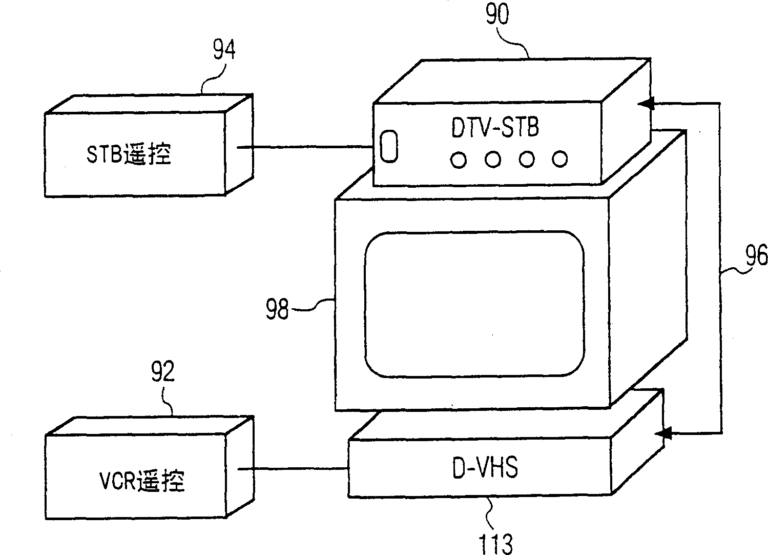
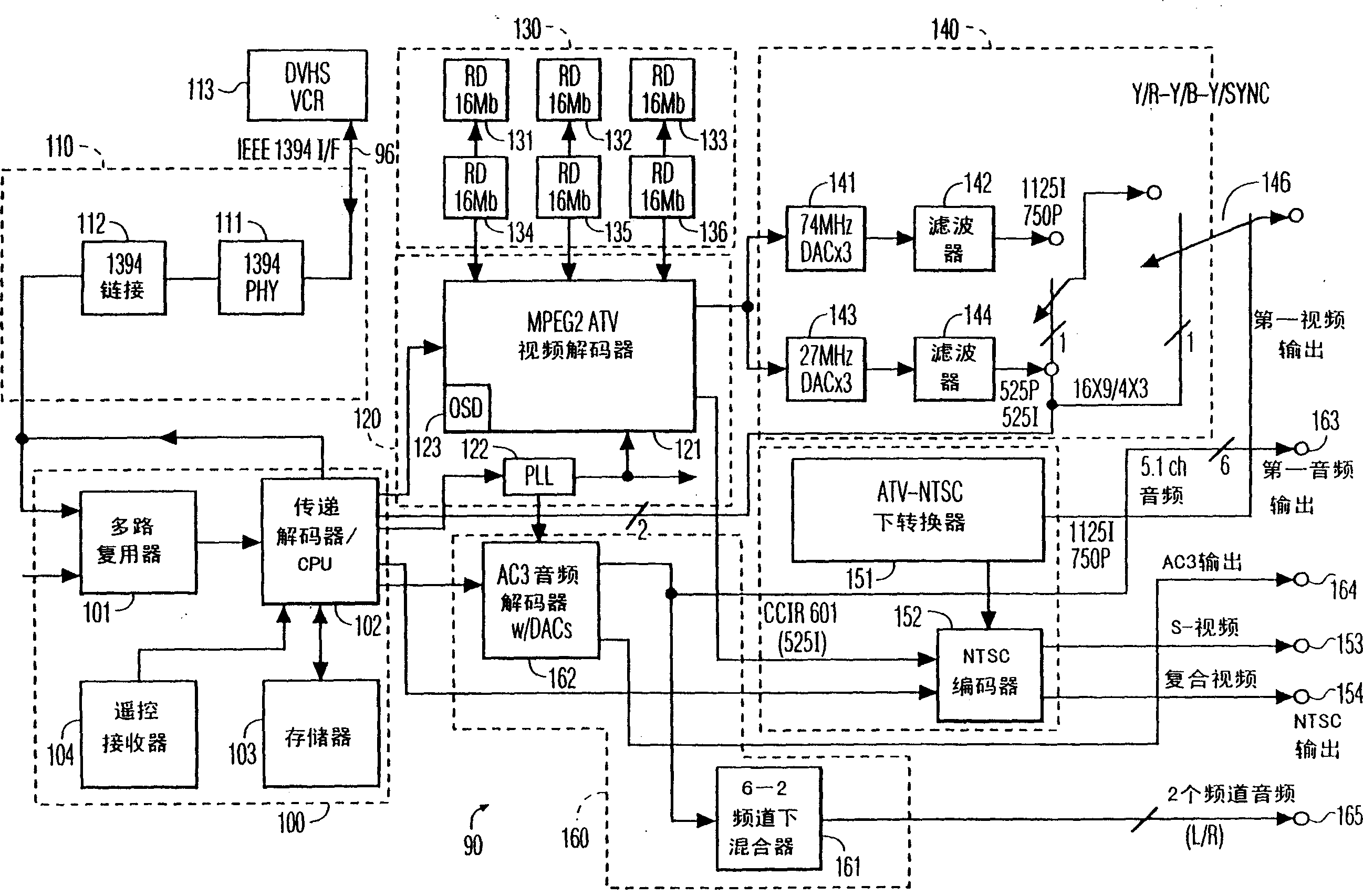
[0018] Figure 1A is a block diagram showing an exemplary system configuration according to the present invention. In this system configuration, a digital television receiver 90 is connected to display video information on a video display device 98 . In the exemplary embodiment of the invention, the digital television receiver 90 is a set top box (STB). The STB 90 is also connected to output an MPEG-2 transport stream to a digital VCR 113 and to receive an MPEG-2 transport stream from a digital VCR 113 . In the exemplary embodiment of the present invention, the digital VCR 113 is a D-VHS device. The digital VCR 113 is connected to the STB 90 via a digital communication channel 96, which in the exemplary embodiment of the invention is an IEEE 1394 bus. As described below, the digital VCR 113 receives and outputs digital television signals via channel 96 synchronously, receives commands and outputs status information asynchronously. as well Figure 1A There are two remote con...


PUM


Abstract

A television receiver which receives an ATSC multi-program stream for a single major channel and generates a status display which displays the major channel identifier and a plurality of indicators, each corresponding to a respective one of the minor channels associated with the major channel. The indicator corresponding to the minor channel that is currently selected is highlighted with respect to the other indicators. The television receiver includes an image format converter and the status display also includes information concerning the format of the received signal and any format conversion that is currently being performed. The television receiver is also coupled to a digital VCR via a digital communications link. The digital television receiver generates a control panel for the digital VCR on the display device of the television receiver, and includes a facility for receiving commands for the digital VCR, sending the commands to the digital VCR via the digital communications link displaying the current status of the digital VCR. The television receiver maintains the status display for the digital VCR, by sending a status change request to the digital VCR immediately after receiving any status change information, whereby the VCR responds to the status change request only on a subsequent change in its operational status.

Description

[0001] This application is a divisional application of the Chinese patent application with application number 99122423.X filed on October 9, 1999. technical field [0002] The present invention relates generally to digital television receivers, and more particularly to a method for displaying status and controlling peripheral devices attached to the digital television receiver and operating in accordance with digital television standards. Background technique [0003] Current analog television systems transmit one program per channel. By tuning the tuner to a desired channel, a selection can be made from the channels being broadcast at any given time. Additionally, the VCR is controlled externally, usually through a peripheral device such as a video cassette recorder (VCR) connected to the television receiver, even though a control or menu screen may be displayed on the television receiver's display device. [0004] There exist digital television systems which transmit mult...

Claims


Application Information

Patent Timeline
IPC IPC(8): G09G5/00H04N5/445H04N5/775H04N21/41H04N21/485H04N21/488
CPCH04N7/0122H04N5/44513H04N21/4104H04N5/775H04N21/488H04N21/485H04N21/4135H04N21/4312H04N21/43632H04N21/47H04N5/445
Inventor 乔治·劳纳斯佩里·邓恩戴维·古德温迈克尔·卡恩马修·库雷里谢尔盖·丹尼尔丘克
Owner PANASONIC INTELLECTUAL PROPERTY CORP OF AMERICA
Learn More