Adhesion catching apparatus

A utensil, adhesive layer technology, applied in applications, animal traps, devices for catching or killing insects, etc., can solve the problem of mouse escape, a lot of dust and oil attached, small animals cannot be strongly adhered, etc. problem, to achieve the effect of high capture rate

Inactive Publication Date: 2004-05-19
IKARI SHODOKU
View PDF2 Cites 4 Cited by
  • Summary
  • Abstract
  • Description
  • Claims
  • Application Information

AI Technical Summary

Problems solved by technology

[0003] However, on the hands and feet of small animals such as mice, there is a lot of dust and oil, etc.
Since such dust and oil prevent the adhesive layer from adhering small animals, there are cases where small animals cannot be strongly adhered to the adhesive layer
In addition, when the foot strength of a mouse etc. is unexpectedly strong, the adhesive layer attached to it is peeled off, and the mouse may escape
Therefore, there are many cases where the existing adhesion capture device cannot capture small animals

Method used


Image

  • Adhesion catching apparatus
  • Adhesion catching apparatus
  • Adhesion catching apparatus

Examples


Embodiment 1

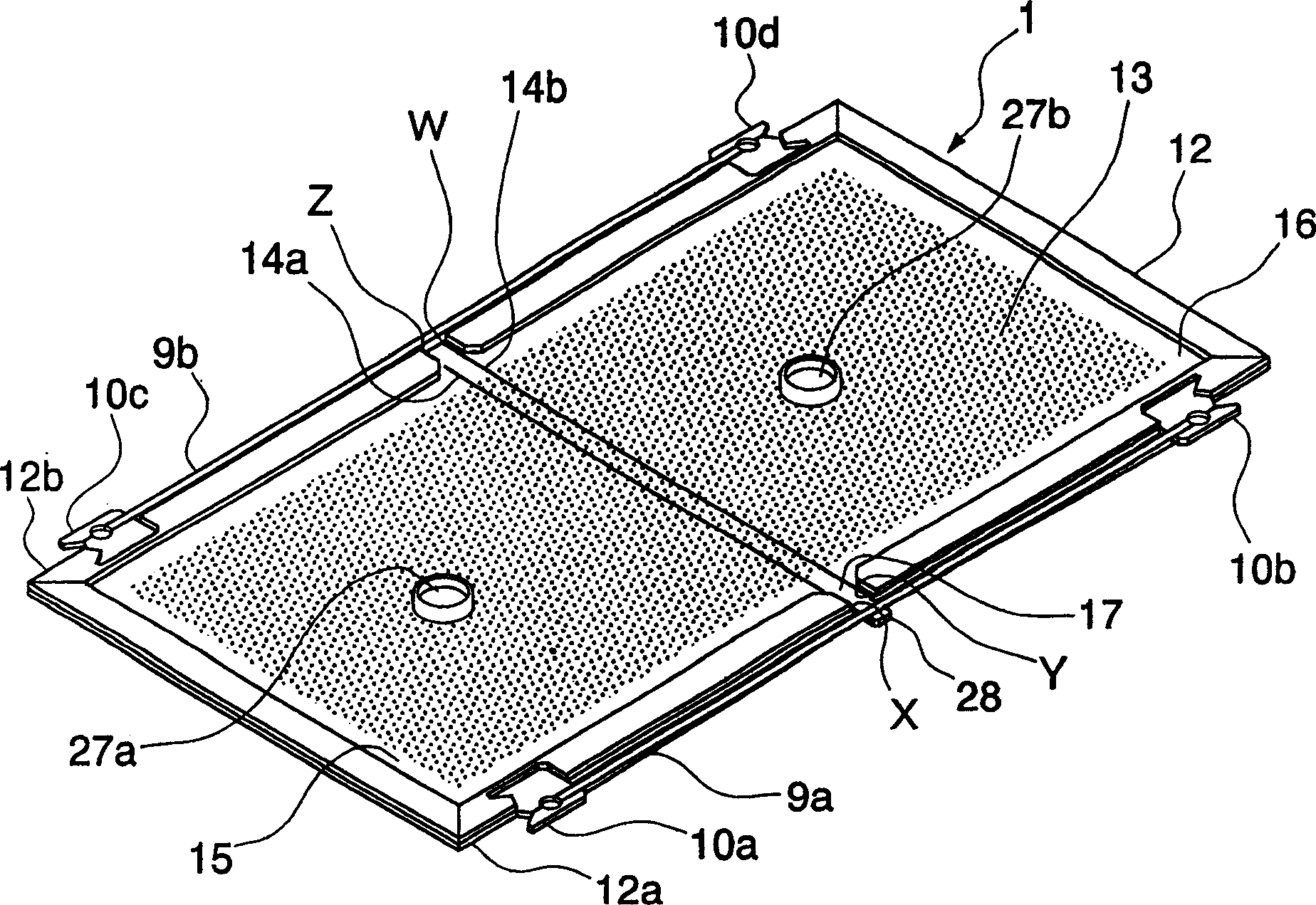
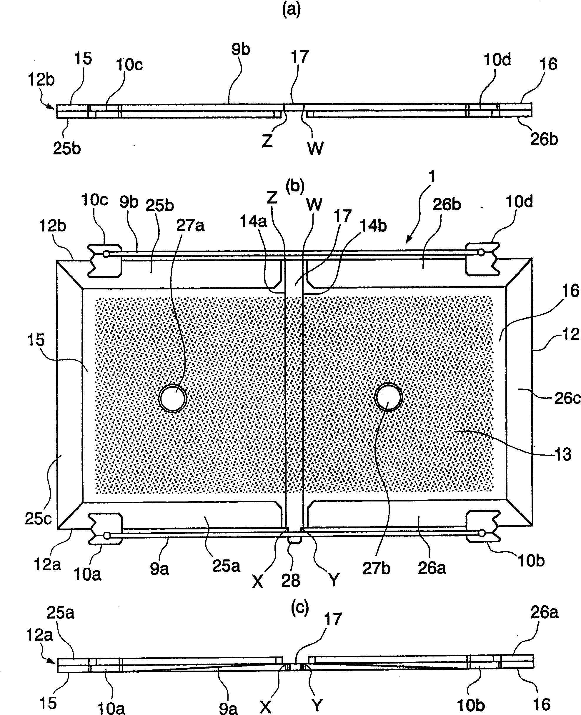
[0030] figure 1 and figure 2 The adhesion-trapping device 1 of Example 1 of the present invention arranged in a planar shape is shown. figure 1 and figure 2 (a) to (c) are a perspective view, a rear view, a plan view, and a front view showing the adhesion trapping tool 1, respectively.

[0031] The adhesion trapping tool 1 of this embodiment has a structure in which an adhesive layer 13 is basically provided on a rectangular base plate 12 to which elastic bodies 9a and 9b are mounted on both sides of a long side portion.

[0032] The base plate 12 is divided into two capturing surfaces (left side part 15 and right side part 16 ) by hinge part 17 formed by two parallel creases 14 a and 14 b perpendicular to the long side.

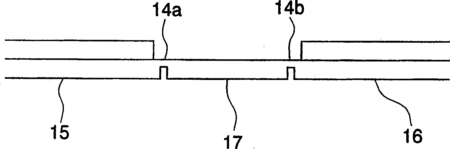
[0033] For example image 3 As shown, the creases 14a and 14b are formed such that the substrate 12 is bent in a direction in which two folds are formed with the adhesive layer 13 on the inside. In addition, if image 3 The creases 14a and 14b formed...

Embodiment 2

[0060] Combine below Figure 6 The second embodiment of the adhesion capture device of the present invention is introduced.

[0061] In the following examples, with Figure 1~5 Components corresponding to the first embodiment shown are denoted by the same symbols, and their detailed descriptions are omitted.

[0062] Figure 6 and 7 The adhesion trapping tool 11 of the second embodiment set in a flat state is shown. Figure 6 , Figure 7 (a) to 7(c) are the perspective view, rear view, top view and front view of the adhesion trapping tool, respectively.

[0063] The shape of the elastic body and the elastic body engaging part of the adhesion capturing device 11 of this embodiment is different from that of the first embodiment.

[0064] In this embodiment, the elastic body engaging parts 18a and 18b on the lower side 12a side of the left side part 15 and the right side part 16 are provided on the inner side in a shape cut obliquely from the outer edge of the lower side 12...

Embodiment 3

[0076] Combine below Figure 9 The third embodiment of the adhesion capture device of the present invention is introduced.

[0077] Figure 9 The adhesion-trapping tool 11 shown is different from the adhesion-trapping tool 11 of the above-mentioned second embodiment in that it has legs 35 and 36 on the undersides of the left side 15 and the right side 16 of the substrate 12 .

[0078] By providing the leg parts 35 and 36, the board|substrate 12 and the hinge part 17 can be installed in the state which floated from the ground. In addition, when the small animal touches between the feet 35 and 36, the feet 35 and 36 act as the fulcrum of the lever, and the base plate 12 becomes a valley shape with the hinge 17 as the base, so it is easier to fold in two. state.

[0079] There is no particular limitation on the setting positions of the feet 35 and 36. The closer to the outer edge of the short side of the base plate, the greater the distance between the feet 35 and 36, which in...


PUM


Abstract

Provided is an adhesive trapping device having a high trapping rate of small animals such as mice and the like and hardly generating malfunction and failure in action. The adhesive trapping device 1 has an adhesive layer 13 on the upper surface of a base board 12 which can be folded in half. Elastomer engaging units 10a, 10b are installed on the left face 15 and the right face 16 of the lower side 12a of the base board 12 and elastomer engaging units 10c, 10d are installed to the left face 15 and the right face 16 of the upper side 12b. The elastomer engaging unit 10a and the elastomer engaging unit 10b are connected with an elastomer 9a which passes outside of intersections X and Y on the lower side 12a. The elastomer engaging unit 10c and the elastomer engaging unit 10d are connected with an elastomer 9b which passes outside of intersections Z and W on the upper side 12b.

Description

technical field [0001] The present invention relates to an adhesive trap for trapping small animals such as mice. Background technique [0002] In order to capture small animals such as rats, adhesive traps that form an adhesive layer on a substrate have been used. The sticky trapping tool has the sticky layer arranged upwards, and when the small animal passes through the sticky layer, the sticky layer sticks to the foot of the small animal, thereby capturing the small animal. [0003] However, on the hands and feet of small animals such as mice, a lot of dust and oil are attached. Since such dust and oil prevent the adhesive layer from adhering small animals, there are cases where small animals cannot be strongly adhered to the adhesive layer. In addition, when the legs of mice etc. are unexpectedly strong, the adhered adhesive layer may peel off and the mice may escape. Therefore, there are many cases where the existing sticky trapping tools cannot catch small animals. ...

Claims


Application Information

Patent Timeline
Patent Type & Authority Applications(China)
IPC IPC(8): A01M1/14A01M23/00
Inventor 黑泽聪树谢林谷川力富冈康浩
Owner IKARI SHODOKU
Why Eureka
Try Eureka