Threaded crown for timepiece

A crown and timepiece technology, which is applied to the mechanical device for time indication, the mechanical device for adjusting the time indication device, and the mechanically driven clock, etc., can solve the problems of unfavorable aesthetic appearance and unsuitability of the casing.

Inactive Publication Date: 2004-06-16
KS 22
View PDF0 Cites 68 Cited by
  • Summary
  • Abstract
  • Description
  • Claims
  • Application Information

AI Technical Summary

Problems solved by technology

However, the method of assembling such crowns is not suitable for screw-up crowns having a marking or a design such as a logo, superscript or the like
In fact, the known production methods do not always allow the crown, after being unscrewed, to enter into a predetermined orientation relative to the case, which is not conducive to the stability of the case when inscriptions are made on the end face of the crown. aesthetic appearance
Of course this is unacceptable when such a crown is fitted to a high quality luxury item

Method used


Image

  • Threaded crown for timepiece

Examples


Embodiment Construction

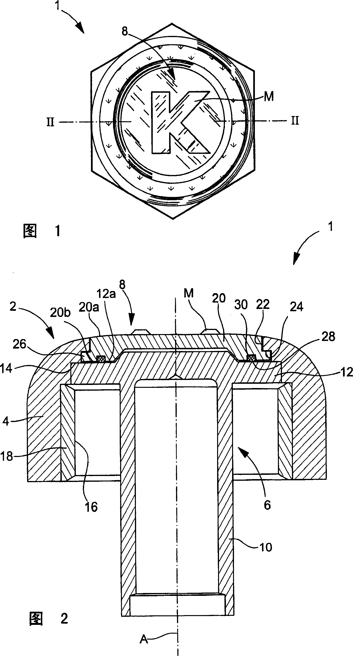
[0012] Figures 1 and 2 show a screw-on crown, generally indicated by the reference number 1, for screwing onto a threaded pipe (not shown) which is driven into a In the central part of the watch case (not shown).

[0013] The crown 1 comprises a first part comprising a head 2 extending from a lateral skirt 4 surrounding a central part 6 fastened to the head. The head 2 includes an end face or front surface 8 on which a design such as a logo or trademark M is implemented by printing or engraving or in any suitable manner. The central part 6 is intended to be connected to the movement of the timepiece by means of a mainspring or time setting lever in a conventional manner. In the illustrated embodiment, the central part 6 is added to and fastened to the head 2 . The central part 6 comprises a tube 10 fitted with a disc 12 at one end thereof. The central part 6 is generally fastened into a first shoulder 14 provided in the head 2 by eg welding, gluing, crimping or any suitable...


PUM


Abstract

The invention concerns a screw-on crown for a timepiece, including a head, a central portion and a lateral skirt, said head including an end face bearing a design, characterized in that the end face includes a substrate onto one face of which said design is applied, in that said substrate is mounted so as to move in rotation in said head and in that the crown further includes braking means arranged for holding said substrate in different angular orientations with respect to the head about the rotational axis of the crown.

Description

technical field [0001] The present invention relates to screw-on or threaded crowns for timepieces, and more particularly to such crowns which include a design or logo on their end face and wherein said design can be oriented as desired . Background technique [0002] Generally, the screw-on crown is installed on the watch to improve the water resistance of the watch at the winding stem or control shaft. The particularity of this crown is that it can occupy an unscrewed position, in which the watch can be wound up, adjusted to the correct time, etc., and a screwed-in position, in which the watch The crown is screwed and locked onto a tube that is driven into the middle part of the case of the watch to compress a gasket, thus improving the water resistance of the watch. This screwed-on position thus corresponds to the normal position when the watch is worn. [0003] The production and assembly of these screw-on crowns on watch cases is known. However, the method of assemb...

Claims


Application Information

Patent Timeline
Patent Type & Authority Applications(China)
IPC IPC(8): G04B3/04G04B27/00G04B37/10
CPCG04B3/041G04B37/103
Inventor R・埃科菲特S・温格
Owner KS 22
Why Eureka
Try Eureka