
Rear chain shifter for bicycle

A technology for rear derailleurs and bicycles, which can be applied to vehicle parts, vehicle gearboxes, chain/belt transmissions, etc., and can solve problems such as difficulty in tightening nuts.

Inactive Publication Date: 2004-06-23
SHIMANO INC
View PDF1 Cites 7 Cited by
  • Summary
  • Abstract
  • Description
  • Claims
  • Application Information

AI Technical Summary

Problems solved by technology

However, in this case, it is necessary to rotate the nut while clamping the wheel and preventing the head from turning, so it is difficult to tighten the nut.

Method used


Image

  • Rear chain shifter for bicycle
  • Rear chain shifter for bicycle
  • Rear chain shifter for bicycle

Examples


Embodiment Construction

[0033] overall composition

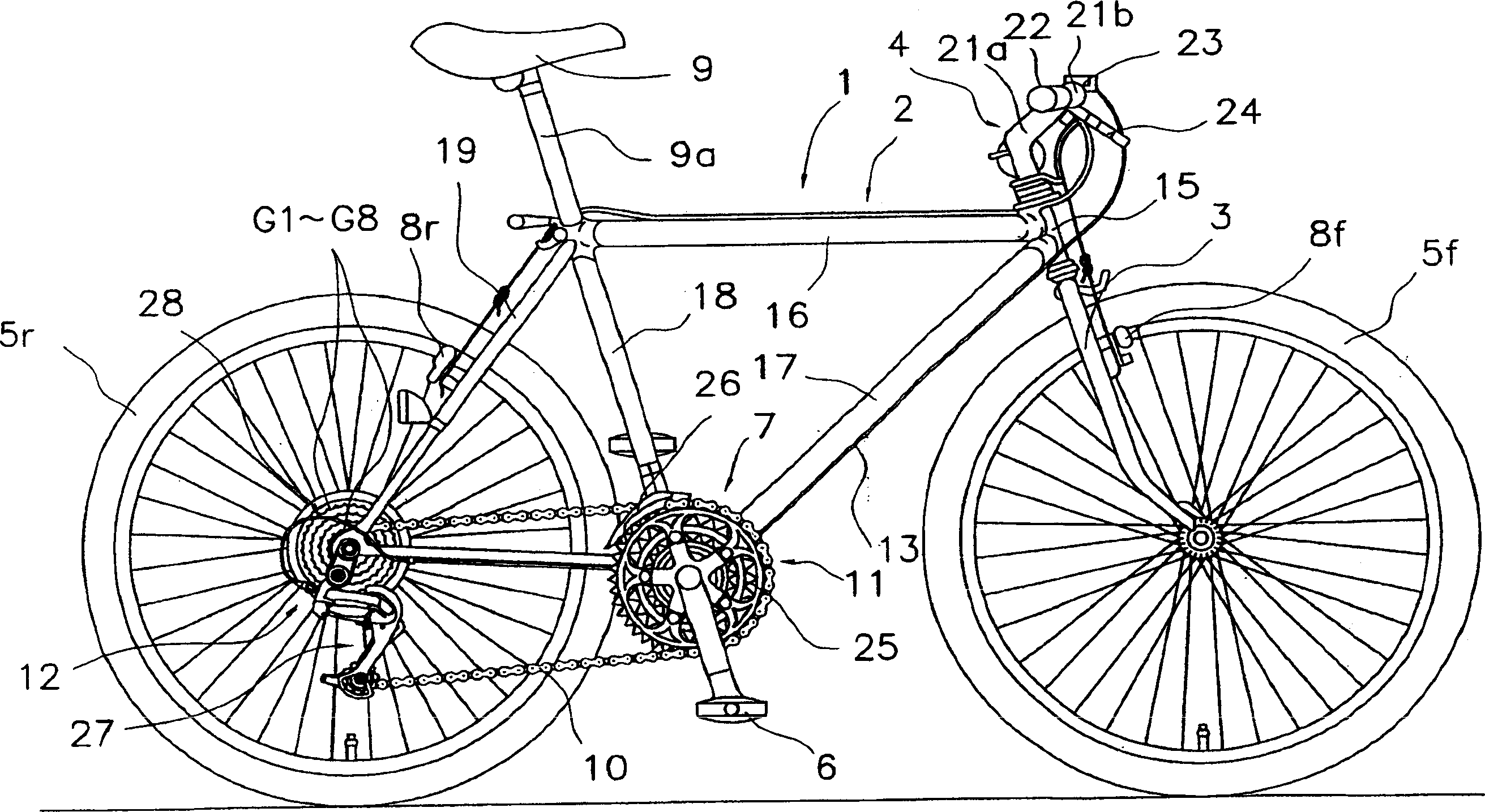
[0034] figure 1 A bicycle to which an embodiment of the present invention is attached is shown. The bicycle has: a frame 1 having a frame body 2 and a front fork 3; a handle portion 4; a front wheel 5f; a rear wheel 5r; a drive unit 7 for transmitting the rotation of the pedal 6 to the rear wheel 5r; front and rear brake devices 8f , 8r.

[0035] The frame body 2 is composed of a top tube 15 that is rotatably installed on the shaft system that is inclined to the front of the front fork 3, an upper tube 16, a lower tube 17, and a front triangle of the support tube 18. Part and the known rhombus frame body formed by the rear triangular part with the seat support 19 and the chain stay 20.

[0036] The seatpost 9a to which the saddle 9 is attached is attached to the stand tube 18 so that the vertical position can be adjusted. A front wheel 5f is attached to the lower end of the front fork 3 . The drive unit 7 is provided at the lower end of the st...


PUM


Abstract

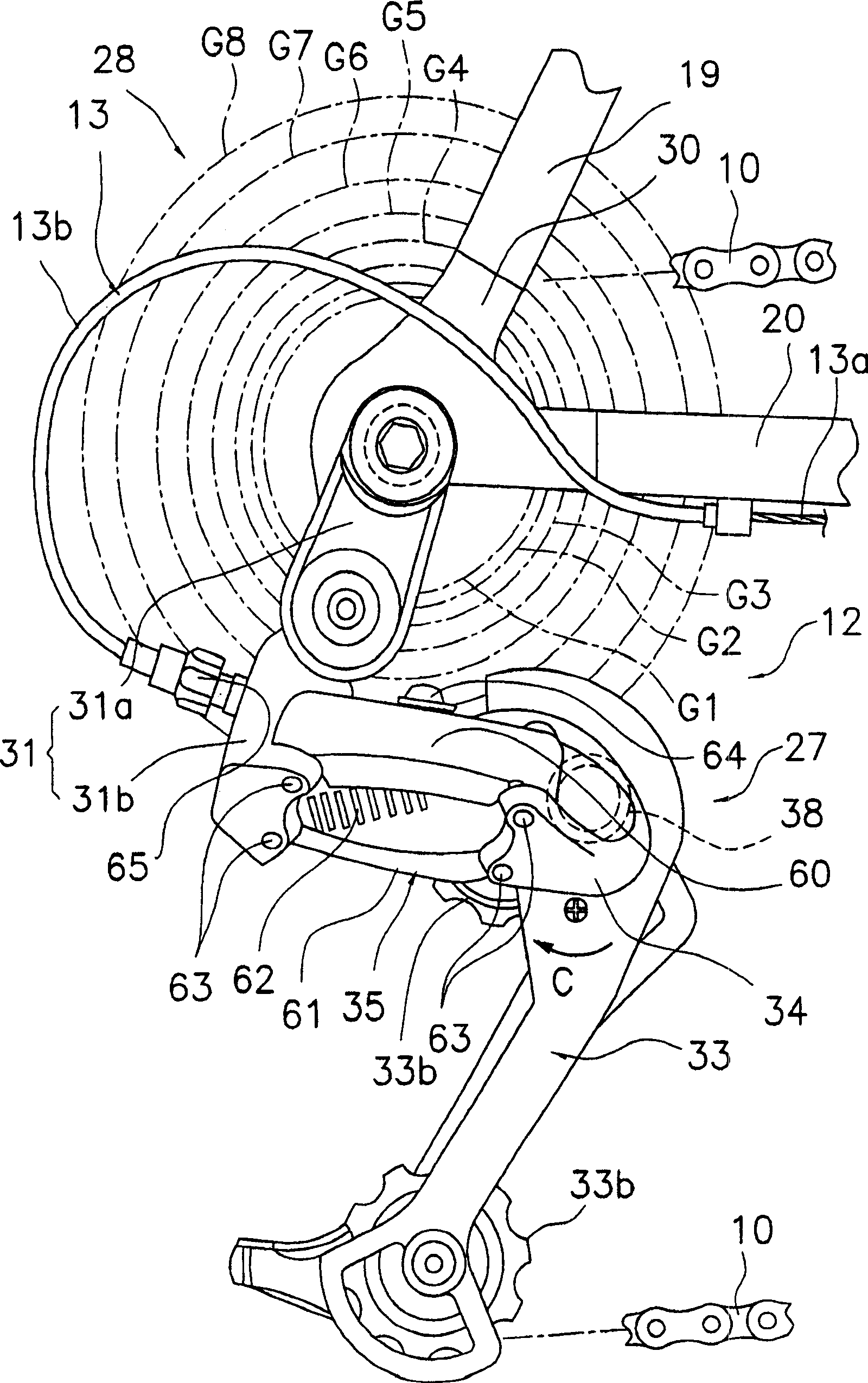
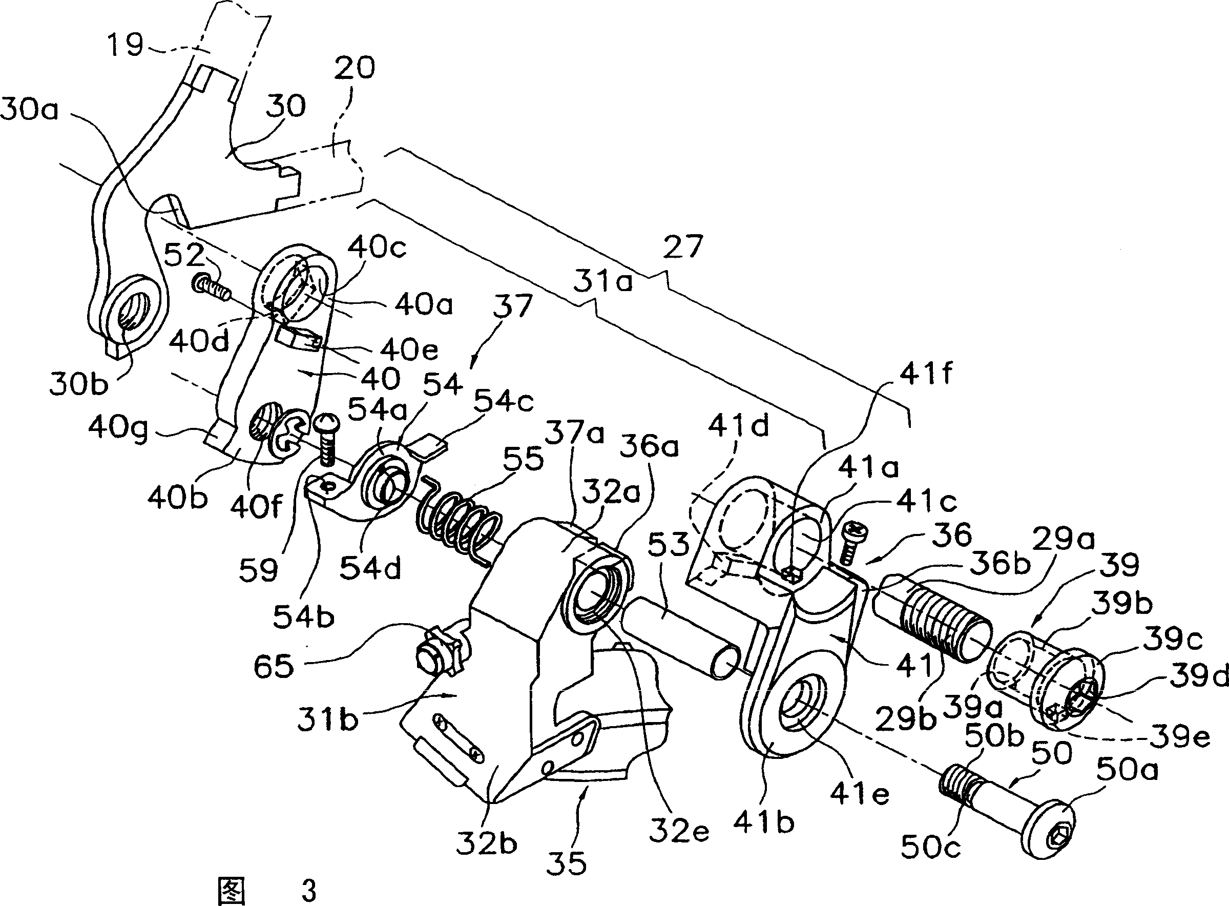
The rear derailleur 27 is locked to a rear nail 30 in a removable manner by the hub shaft 29a having male screws 29b formed at the mounting position of the hub shaft 29a of the rear hub 29 of the bicycle. The derailleur comprises a base member 31, a chain guide 33, a movable member 34, and a link mechanism 35. The base member has locking parts 40a, 41a each having a female screw 39a engaging with the male screw and locked to the rear nail in a removable manner, and a turn preventive projection 40d engaging with a fitting slot 30a to prevent the base member from turning. The chain guide guides a chain to a plurality of sprockets and is connected to the hub shaft by the movable member freely swingably. The link mechanism connects the movable member to the base member to allow the movable member to move relatively to the base member.

Description

technical field [0001] The present invention relates to a derailleur, in particular to a plurality of derailleurs which are detachably fixed to the rear end of the frame at the installation position of the hub axle of the rear hub of a bicycle, and which are used to hang on the rear hub and have different numbers of teeth. A rear derailleur for a bicycle with a chain on either sprocket. Background technique [0002] A rear derailleur for an external derailleur for a bicycle hangs a chain on any one of a plurality of sprockets mounted on a rear hub. A conventional derailleur includes a base member detachably fixed to a rear end of a frame, a chain guide for guiding a chain to a plurality of sprockets, a movable member, and a link mechanism. [0003] Rear claws for attaching the rear hub are formed at the rear end of the frame, and the base member is fixed to the rear claws at the rear end of the frame with nuts together with the hub shaft (for example, refer to Patent Docume...

Claims


Application Information

Patent Timeline
IPC IPC(8): B62M9/125B62M9/126
CPCB62M9/125
Inventor 谢花聪原宣功
Owner SHIMANO INC
Learn More