
Suction cleaner

A technology for vacuum cleaners and dust collection rooms, which is applied to the installation of vacuum cleaners, electrical equipment, and cleaning equipment, etc. It can solve problems such as affecting the appearance and unpleasantness of users, and achieve the effects of reducing damage to the appearance, suppressing scratches, and reducing damage

Inactive Publication Date: 2005-03-02
SANYO ELECTRIC CO LTD
View PDF0 Cites 0 Cited by
  • Summary
  • Abstract
  • Description
  • Claims
  • Application Information

AI Technical Summary

Problems solved by technology

However, with such a structure, scratches will be produced on the outside of the main body of the vacuum cleaner due to repeated contact with the guide surface, especially if the scratches occur on the upward surface during use, it will affect the appearance and make the user feel unpleasant.

Method used


Image

  • Suction cleaner
  • Suction cleaner
  • Suction cleaner

Examples


Embodiment Construction

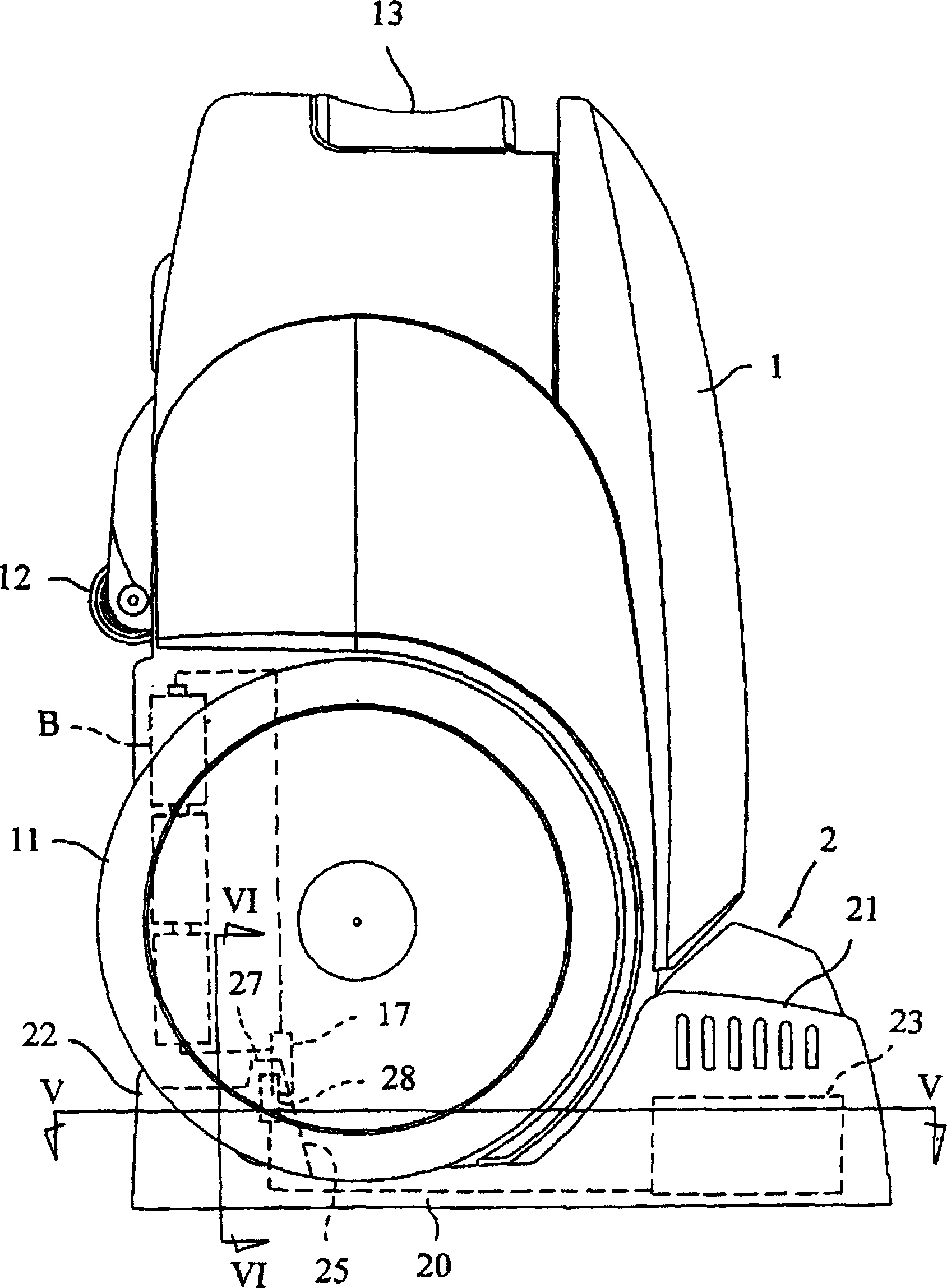
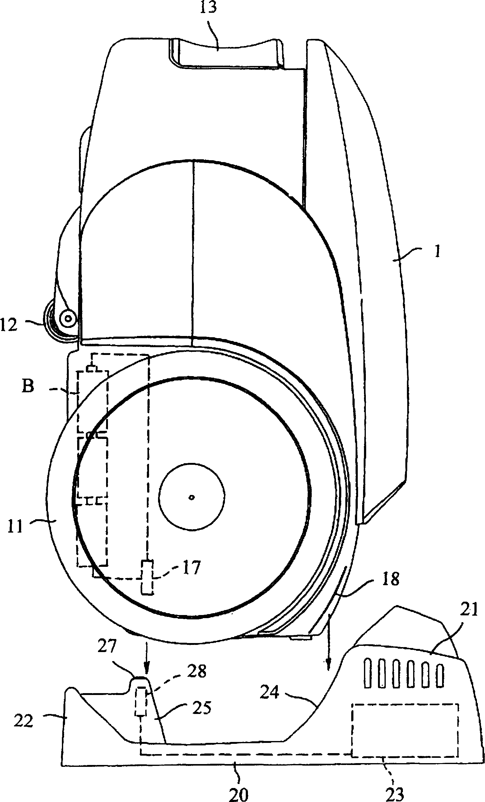
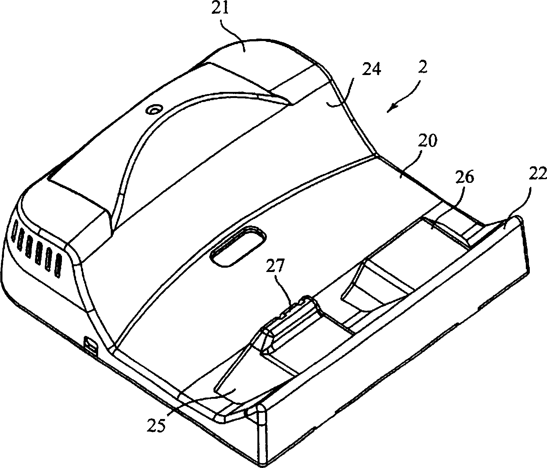
[0040] figure 1 It is a side view of the main part of the vacuum cleaner of the present invention, 1 in the figure is the main body of the vacuum cleaner, and 2 in the figure is the charging stand.

[0041] Above-mentioned vacuum cleaner main body 1 has a left and right pair of large-diameter rear wheels 11,11 (only one is shown in the figure) on its outside, and the small-diameter front wheel 12 that is made of castors, and there are electric fans and electric fans for air suction inside it. The dust collection chamber (all not showing among the figure) that catches dust usefulness, simultaneously, have suction port 13 and exhaust port 14 (referring to Figure 4 ), during use, the above-mentioned suction port 13 is connected with the suction pipe and the dust collector by a flexible suction hose.

[0042] Inside the vacuum cleaner main body 1, such as figure 1 and figure 2 As shown by the dotted line in , a battery B as a power source is housed inside, and the electric cu...


PUM


Abstract

The present invention is to surely guide a vacuum cleaner body which is mounted on a charging base to a correct mounting location while suppressing the generation of scars on the external surface. A guide rib 18 is projected from the upper surface of the rear section of the vacuum cleaner body 1 which is guided by the guide surface 24 of the charging base 2. Then, the vacuum cleaner is constituted in such a manner that when the vacuum cleaner body 1 is placed on the charging base 2, the guide rib 18 comes into contact with the guide surface 24 and is guided. In this case, scars which are generated accompanying the guiding action are concentrated to the end edge of the guide rib 18, and are prevented from being generated on the external surface of the vacuum cleaner body 1.

Description

technical field [0001] The present invention relates to a rechargeable vacuum cleaner. The main body of the vacuum cleaner is equipped with a storage battery, and the electric fan is driven by the battery charged from the outside to perform dust suction. Background technique [0002] Vacuum cleaners widely used in general households consist of an electric fan for air suction, a dust collection chamber for collecting dust, a main body of the vacuum cleaner with an air suction port and an exhaust port, and wheels for moving on the ground. A flexible suction hose is connected to the suction pipe with the above-mentioned suction port, and a dust collector detachably mounted on the front end of the above-mentioned suction pipe. The handle moves the main body of the vacuum cleaner on the ground through the rotation of the above-mentioned wheels, and at the same time presses the front end of the vacuum cleaner on the ground to be vacuumed, and drives the electric fan in this state....

Claims


Application Information

Patent Timeline
Patent Type & Authority Patents(China)
IPC IPC(8): A47L9/28A47L5/22A47L5/28A47L9/00
CPCA47L5/362A47L9/2873
Inventor 田中孝森田明宏吉田润森好弘土肥宪一郎小林利造丰冈贤次
Owner SANYO ELECTRIC CO LTD
Learn More