

Copper receptacle assembly with sectional pins
A technology of special-shaped needles and components, applied in the direction of contact parts, etc.
Inactive Publication Date: 2004-07-07
上海旭隆电气有限公司
View PDF0 Cites 0 Cited by
- Summary
- Abstract
- Description
- Claims
- Application Information
AI Technical Summary
Problems solved by technology
Due to the adoption of the above scheme, it is not difficult to conclude that the present invention has the following beneficial effects. The present invention has a reasonable structure and ingenious conception, which can better decompose the tension of thermal expansion and contraction of the plug end, is convenient to operate, and effectively overcomes the traditional wiring method. The defects of exposed pile heads and poor safety provide a strong guarantee for the advancement of electrical equipment towards insulation, and are of great promotion value
Method used
View moreImage
Smart ImageViewing Examples

Examples
Embodiment Construction
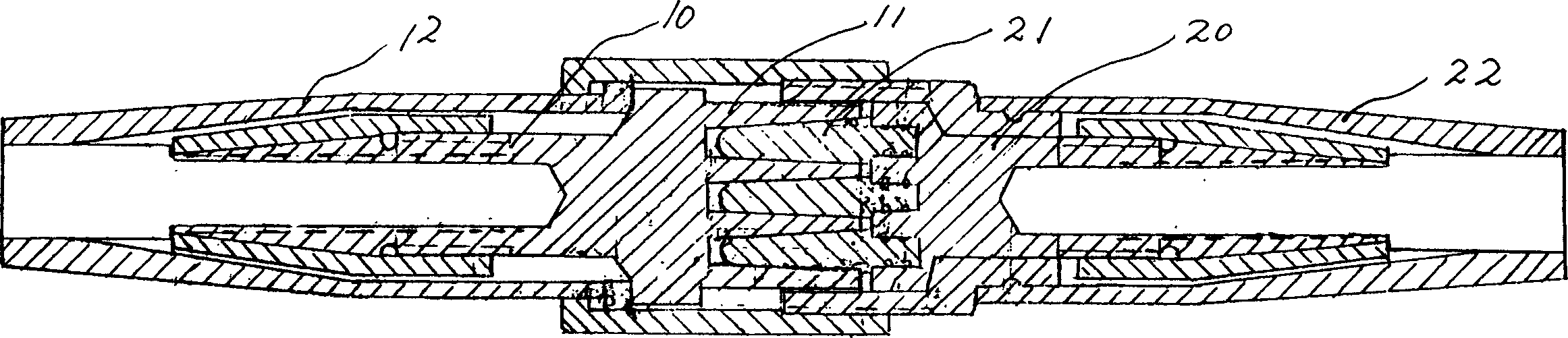
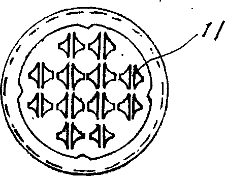
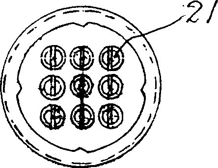
[0008] In the figure, a special-shaped pin-type copper connector assembly is mainly composed of a connector 10 and a plug-in 20. The upper end of the connector 10 is provided with a cross-conical needle body 11, and the adjacent two ends of the cross-conical needle body form four points. One of the conical grooves is screwed with a cap 12 at the lower end, and the upper end of the plug-in 20 is provided with a conical needle body 21 matching the shape and quantity of the conical groove formed by the connector 10 , and the lower end is also screwed with a cap 22 . When in use, the two can be plugged together.
Login to View More PUM
 Abstract
An abnormity pin copper connection groupware mainly consists of female connector and male connector. Its feature is: the said female connector has cross taper pin body, the neighbouring two end of cross taper pin body forms one fourth taper slot, the up end of male connector has the taper pin body matching the taper slot of female connector. This invention can decompose the tension caused by hot expansion and cold contraction, overcome the defect of peg head exposure and low safety existed in traditional connection method.
Description
Technical field: [0001] The invention relates to a cable connector, in particular to a pin type cable connector. Background technique: [0002] At present, when connecting wires to high-current electrical equipment, they are connected and fixed by crimping through terminal blocks. Because the wiring pile head is exposed, there are hidden dangers of unsafety, and this connection method is affected by thermal expansion and contraction, and it is easy to produce gaps. After dust enters, a discharge area is formed, which makes the equipment hot and easy to age. Invention content: [0003] The technical problem to be solved by the present invention is to provide a special-shaped pin-type copper connector assembly that can effectively overcome the above defects and facilitate the insulation of equipment. The technical solution adopted by the present invention to solve the technical problem is that a special-shaped pin-type copper plug-in assembly is mainly composed of a connect...
Claims
Login to View More Application Information
Patent Timeline
 Patent Type & AuthorityApplications(China)
IPC IPC(8): H01R13/04H01R13/10
Inventor申小金
Owner上海旭隆电气有限公司