Prestress combined beam, continuous prestress combined beam structure and producing connection method

A composite beam and prestressing technology, which is applied in the direction of load-bearing elongated structural members, structural elements, building structures, etc., can solve problems such as rough appearance, low rigidity ratio, and uneconomical

Inactive Publication Date: 2004-07-14
丘民世
View PDF0 Cites 4 Cited by
  • Summary
  • Abstract
  • Description
  • Claims
  • Application Information

AI Technical Summary

Problems solved by technology

However, the traditional prestressed composite beam is only composed of concrete, so its rigidity is lower than that of a steel structure made of steel, so the remaining clearance must be increased
Therefore, the disadvantage of the conventional prestressed composite beam is that its appearance is rough, and it cannot be used in river-crossing bridges that require sufficient top clearance
In addition, the horizontal steel bars used to join the upper floor slab to the traditional prestressed composite beams must be removed from the finished structure, so that the conventional prestressed composite beams are not economical because the installation in the traditional prestressed composite Prestressed composite beams themselves require more reinforcement

Method used


Image

  • Prestress combined beam, continuous prestress combined beam structure and producing connection method
  • Prestress combined beam, continuous prestress combined beam structure and producing connection method
  • Prestress combined beam, continuous prestress combined beam structure and producing connection method

Examples


Embodiment Construction

[0019] Reference will now be made in detail to specific embodiments of the invention, examples of which are shown in the accompanying drawings, like parts being given like reference numerals throughout.

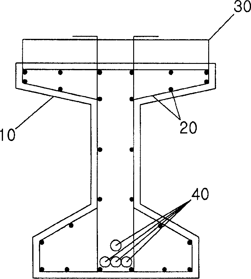
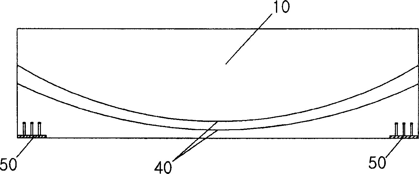
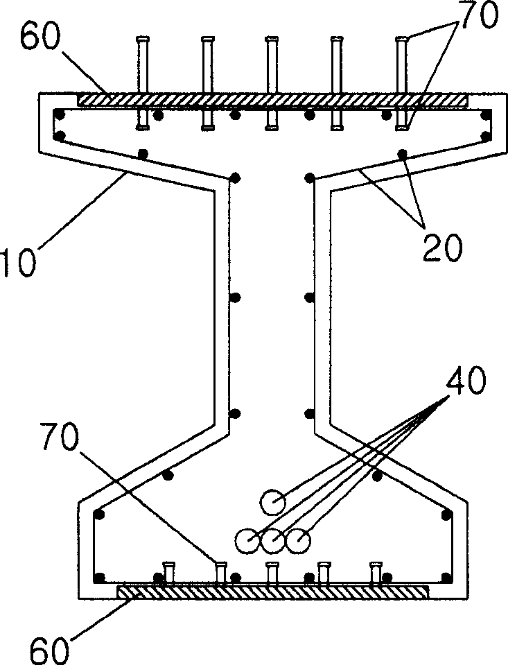
[0020] Figures 2A to 7 is a view of a prestressed composite beam including steel plates. Figure 2A with 2B is a front sectional view of a composite beam with steel plates according to the present invention. Figures 3A to 3C Respectively, the moment diagram and the side cross-sectional diagram of the composite beam with steel plates according to the invention in the case of a simply supported bridge. Figures 4A to 4D Respectively, the moment diagram and the side cross-sectional diagram of the composite girder with steel plates according to the invention in the case of the outer span of a continuous girder bridge. Figures 5A to 5D Respectively, the moment diagram and the side cross-sectional diagram of the composite girder with steel plates according to the invention in...


PUM


Abstract

Disclosed herein are a prestressed composite girder with steel plates, a continuous prestressed composite girder structure with steel plates and methods of fabricating and connecting the same. The prestressed composite girder includes shear reinforcing bars and main reinforcing bars, sheaths, sole plates, and steel plates. The shear reinforcing bars and main reinforcing bars are arranged across the prestressed composite girder. The sheaths are adapted to contain steel wires arranged across the prestressed composite girder. The sole plates are placed at ends of the prestressed composite girder and provided with shear connecting members. The steel plates are placed in upper and lower flanges of the prestressed composite girder and provided with shear connecting members.

Description

technical field [0001] The invention relates to a prestressed composite beam with steel plates, a continuous prestressed composite beam structure with steel plates and a method for manufacturing and connecting the same. Background technique [0002] In the prior art, there are prestressed composite beams formed of concrete without steel plates, and continuous prestressed composite beam structures formed only by using bolts. [0003] Figure 1A with 1B It is a front sectional view and a side sectional view of a widely used traditional prestressed composite beam 10 . [0004] Figure 1A is a front sectional view of a traditional prestressed composite beam 10. refer to Figure 1A , the concrete structure 10 includes: shear bars and main bars 20, horizontal shear bars 30 combining the upper floor slab with conventional prestressed composite beams, and a tension side lower end accommodating steel wires to transmit compressive forces to the concrete structure 10 The casing 40. ...

Claims


Application Information

Patent Timeline
Patent Type & Authority Applications(China)
IPC IPC(8): E04C3/292
CPCE04C3/293E04C3/26E01D2101/285E01D2/02E04C5/0645E04C3/292
Inventor 朴泳济
Owner 丘民世
Why Eureka
Try Eureka