

Slot shaping appts.
A forming device and annular groove technology, applied in the direction of groove needles, metal processing equipment, manufacturing tools, etc., can solve the problem of unstable extrusion force of the metal tube 90, poor engagement, and friction between the metal tube 90 and the pressing roller 82 Problems such as resistance cannot be completely eliminated
- Summary
- Abstract
- Description
- Claims
- Application Information
AI Technical Summary
Problems solved by technology
Method used
Image

Examples
Embodiment Construction
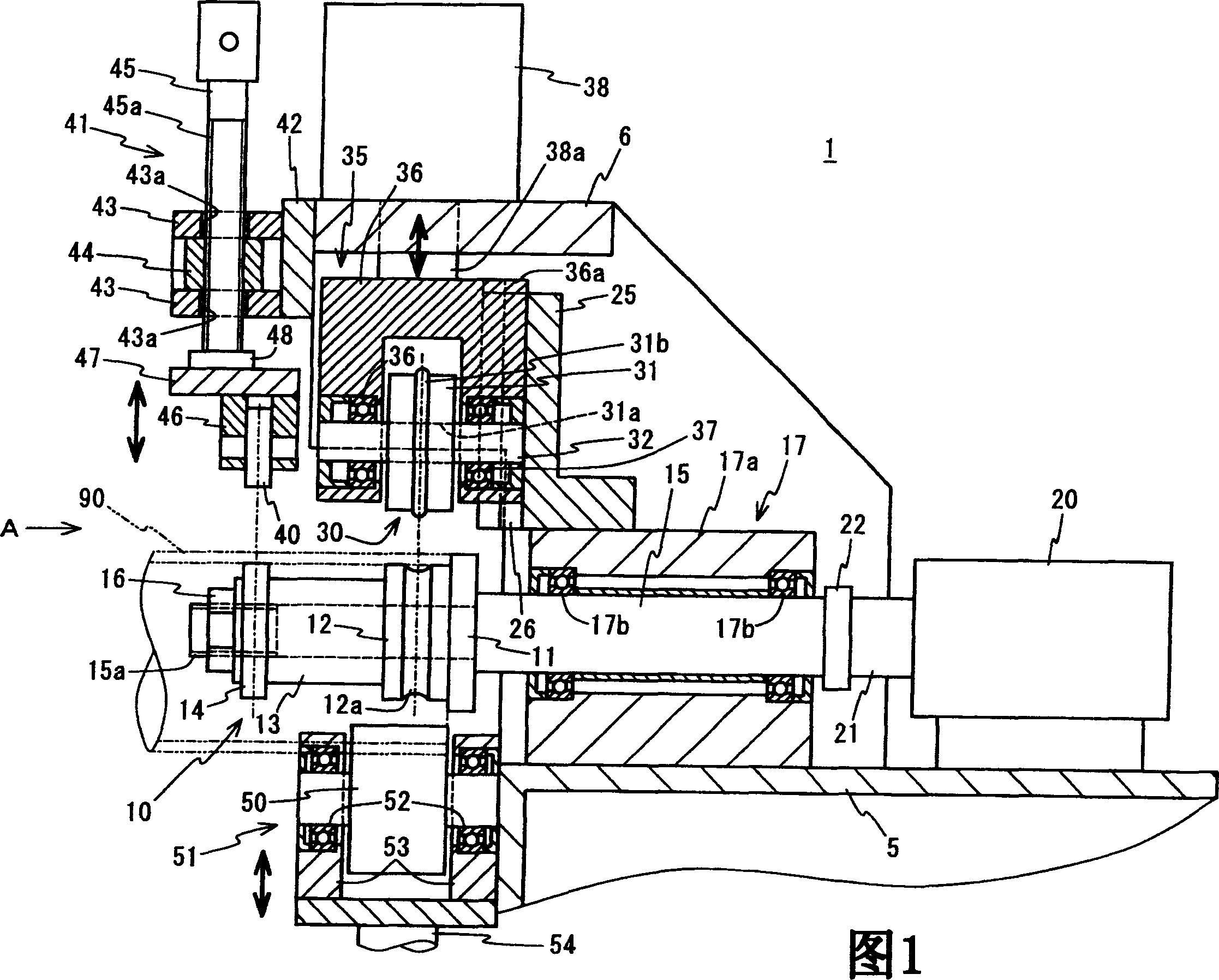
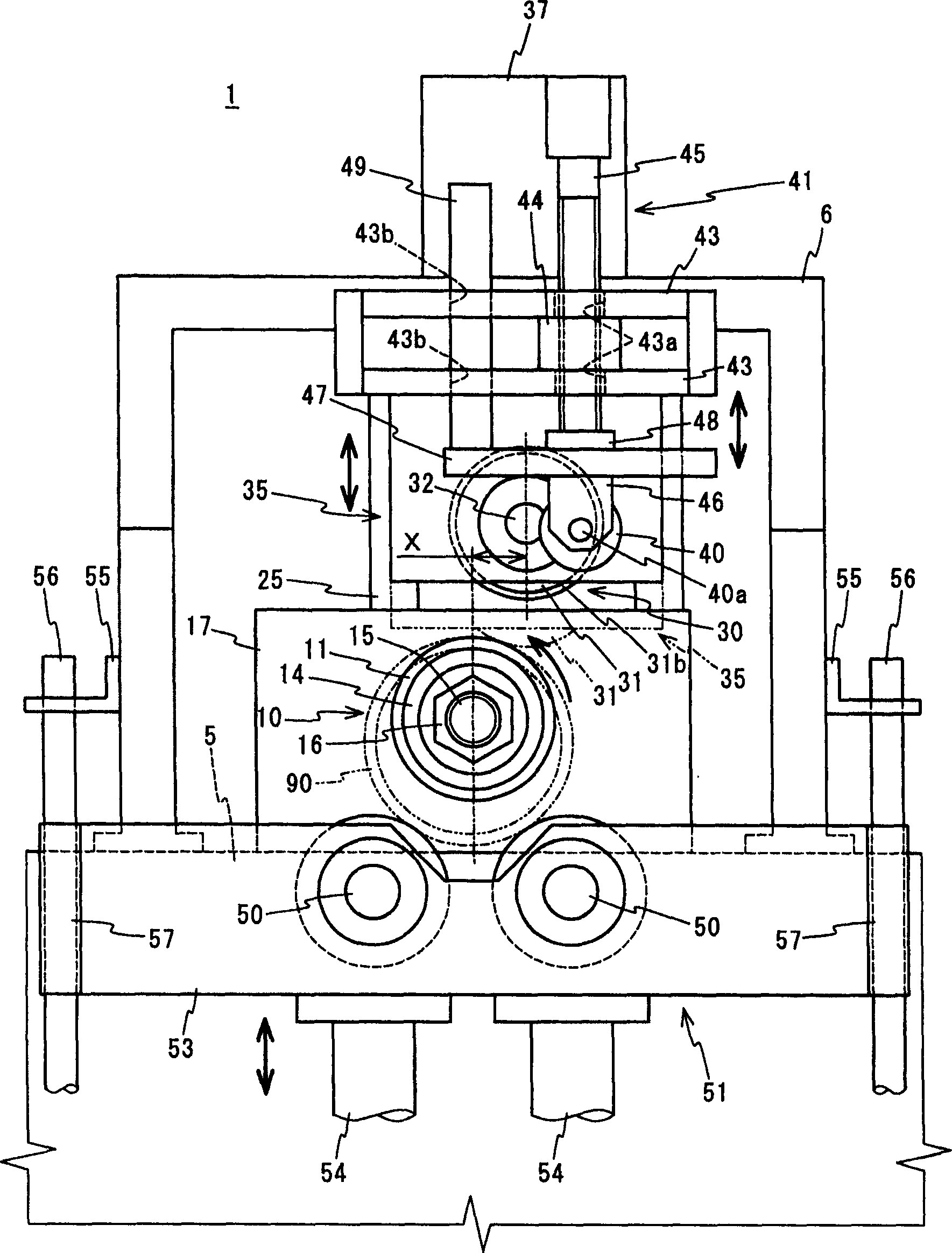
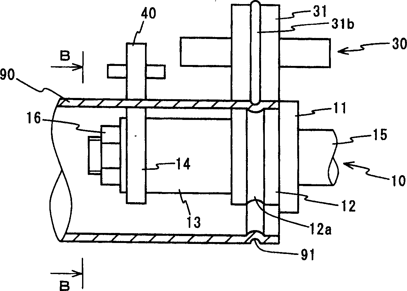
[0046] The specific embodiment of the present invention is described as follows according to the accompanying drawings. Fig. 1 is a cross-sectional view showing a schematic configuration of a groove forming device according to an embodiment of the present invention, figure 2 It is the front view of the direction A indicated by the arrow in Fig. 1. image 3 It is an explanatory diagram showing the state of support and abutment between the backup roller, the pressing roller, the anti-swing roller and the metal pipe according to the present embodiment, Figure 4 for image 3 The cross-sectional view of B-B direction indicated by the middle arrow. In addition, in this example, it is intended to form the annular groove 91 on the aforementioned metal pipe 90 .
[0047] Figure 1 to Figure 4 As shown, the groove forming device 1 of this example has: a support roll 10 that supports the inner peripheral surface of the metal pipe 90 inserted therein, a bearing portion 17 that suppo...
PUM
 Abstract
Description
Claims
Application Information