
Method and appts. for defining position of edge surface of piled, e.g. boardlike objects

An edge and object technology, applied in the direction of optical devices, measuring devices, transportation and packaging, etc., can solve the problems of no precise positioning, changes in the distance between each board and the print head, and poor printing quality

Inactive Publication Date: 2004-08-11
美特索配电盘有限公司
View PDF0 Cites 2 Cited by
  • Summary
  • Abstract
  • Description
  • Claims
  • Application Information

AI Technical Summary

Problems solved by technology

[0003] The disadvantage associated with the marking of the plates is that the stack may not be precisely positioned or the stack is in an inclined position on the conveyor belt, in which case the distance of the edge surfaces of the plates in the stack from the print head and the distance of each plate from the print head head distance may vary
As a result, print quality deteriorates and prints are often misaligned

Method used


Image

  • Method and appts. for defining position of edge surface of piled, e.g. boardlike objects
  • Method and appts. for defining position of edge surface of piled, e.g. boardlike objects
  • Method and appts. for defining position of edge surface of piled, e.g. boardlike objects

Examples


Embodiment Construction

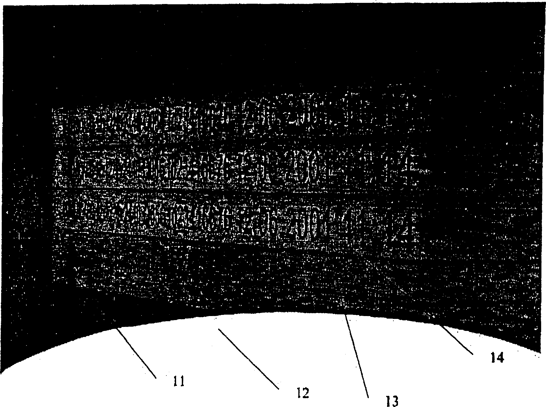
[0010] attached figure 1 The panels 11 are shown stacked on top of each other to form a stack 12 . Printed on the edge 13 of each board 11 is a marking 14 including information such as board type, size, manufacturer, date of manufacture and other similar data. The panel stack 12 may comprise further panels placed one above the other, their height typically being up to eg 1 metre. Furthermore, the stack may include, for example, protective panels above and below it.

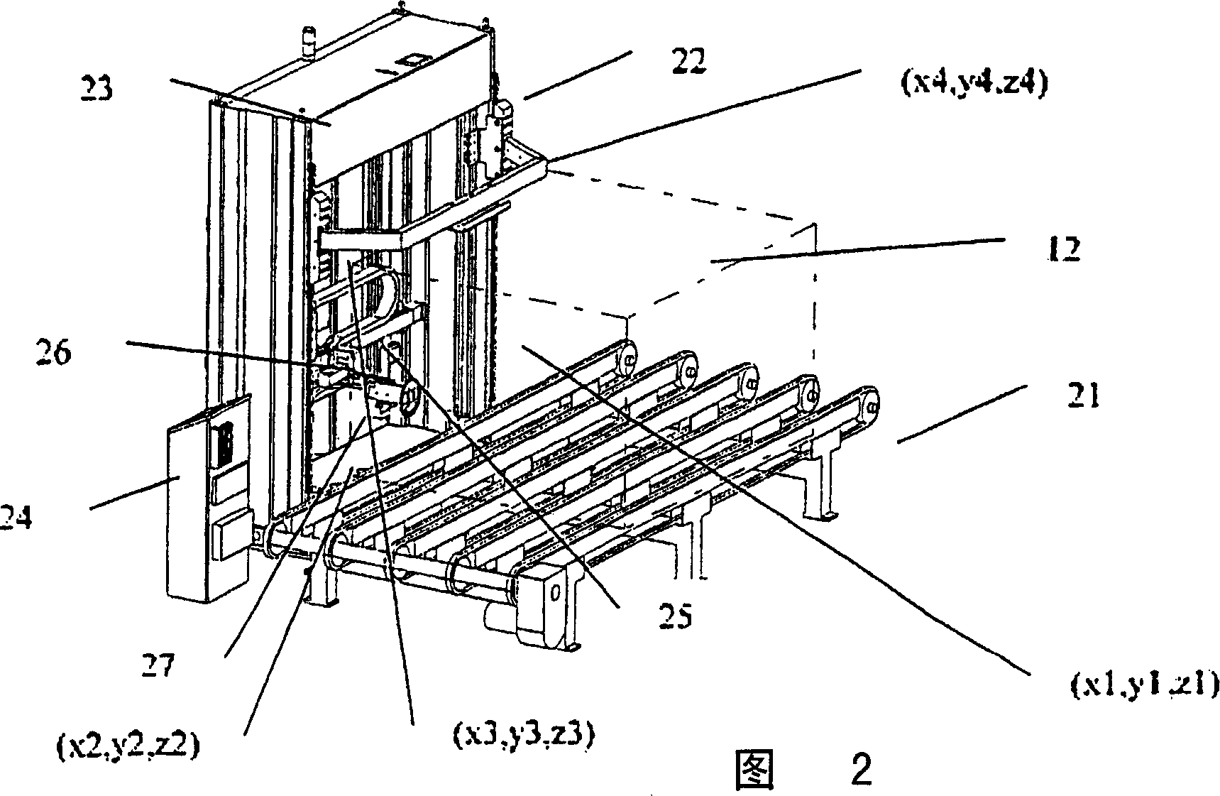
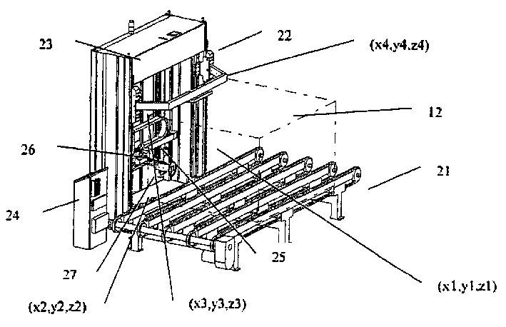
[0011] For example, the plate stack 12 is sent to the measuring and marking station 22 by the chain conveyor 21, wherein as figure 1 Markings are made on the edge of each board as shown. The measuring and marking station comprises a frame part 23, a printing unit 24 for controlling printing, and a system, such as a PLC system (not shown in the figure), for controlling the movable parts of the measuring and marking station. In the frame 23, a guide bar 25 that allows movement in its three main axes x, y, and z ...


PUM


Abstract

Method for determining the position of an edge surface of e.g. boardlike objects (11) arranged in a pile (12) and for marking the objects by means of a print head, in which method the height of the edge surface and / or its position in space is measured by means of a measuring element, in which method the actual deviation of the edge surface (13) from a theoretical basic plane is determined by measuring the spatial coordinates of the edge surface, and the movements of the print head are controlled using the information thus determined so that its distance from the marking point remains at a desired or a substantially constant value.

Description

technical field [0001] The invention relates to a method as defined in the preamble of claim 1 and a device for determining the position of an edge surface of a stack of plate-like objects in order to allow further actions such as marking the plates . Background technique [0002] During the manufacture of different board products, such as cardboard, the boards may be marked to give information such as manufacturer, type, date the board was produced, etc. There are systems in which markings can be made on individual boards, such as the edges of the boards. Systems are also known in which markings are made on the edges of a number of boards when they are placed in a stack. Markings are made using eg inkjet print heads or the like. [0003] The disadvantage associated with the marking of the plates is that the stack may not be precisely positioned or the stack is in an inclined position on the conveyor belt, in which case the distance of the edge surfaces of the plates in t...

Claims


Application Information

Patent Timeline
IPC IPC(8): G01B1/00B41J3/407G01B11/00G01B11/02
CPCG01B11/002G01B11/02B41J3/4073B27M1/00
Inventor K·佩雷莱
Owner 美特索配电盘有限公司
Learn More