
Magnetic resonance oscillation antenna

A magnetic resonance and antenna technology, applied in magnetic resonance measurement, measurement of magnetic variables, measurement devices, etc., can solve problems such as fault sensitivity and blocking switch circuits

Inactive Publication Date: 2004-10-06
SIEMENS HEALTHCARE GMBH
View PDF1 Cites 33 Cited by
  • Summary
  • Abstract
  • Description
  • Claims
  • Application Information

AI Technical Summary

Problems solved by technology

Another disadvantage is that the failure of one switching diode blocks the function of the entire switching circuit, whereby it is inevitable that the structure is sensitive to faults

Method used


Image

  • Magnetic resonance oscillation antenna
  • Magnetic resonance oscillation antenna
  • Magnetic resonance oscillation antenna

Examples


Embodiment Construction

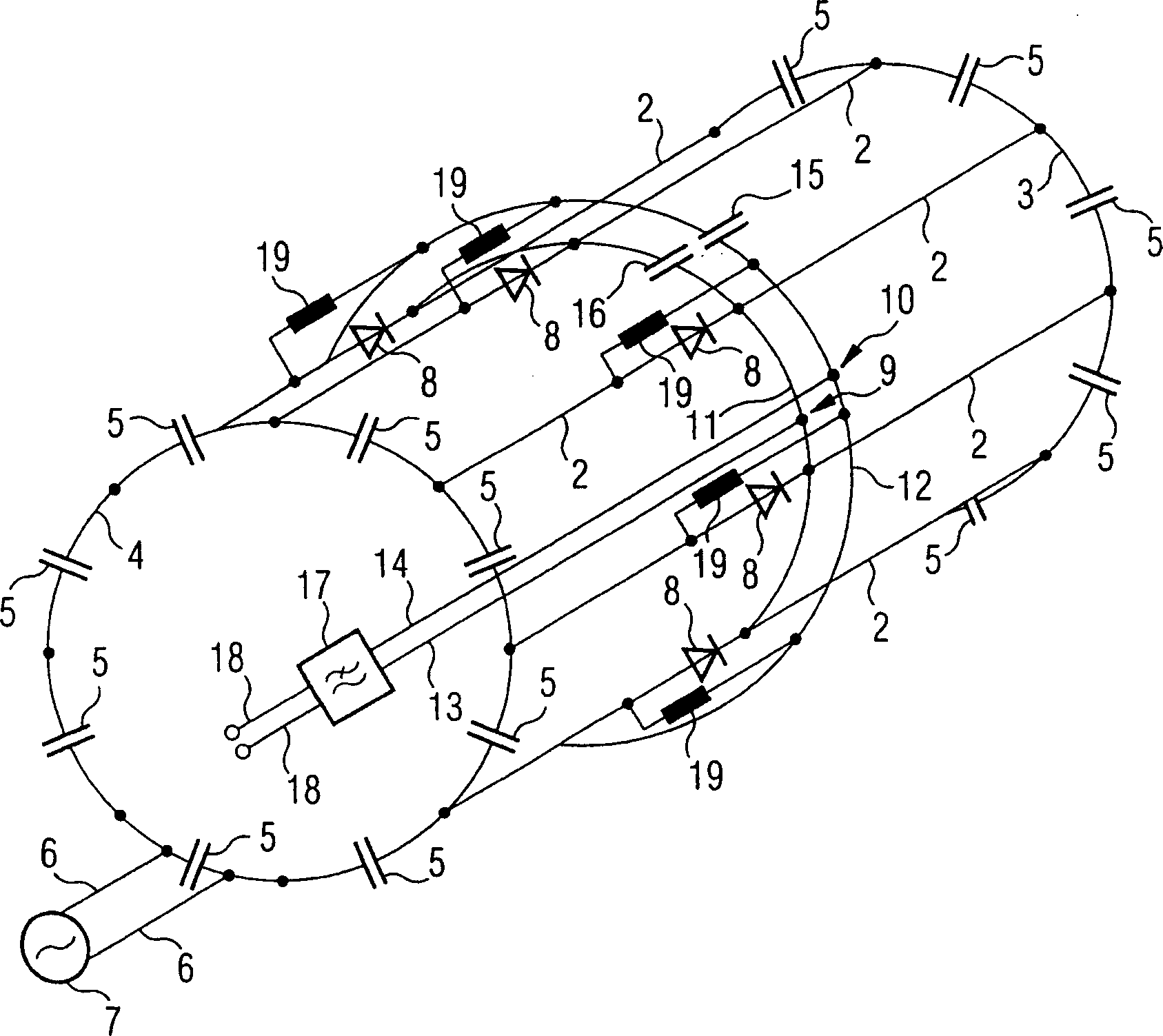
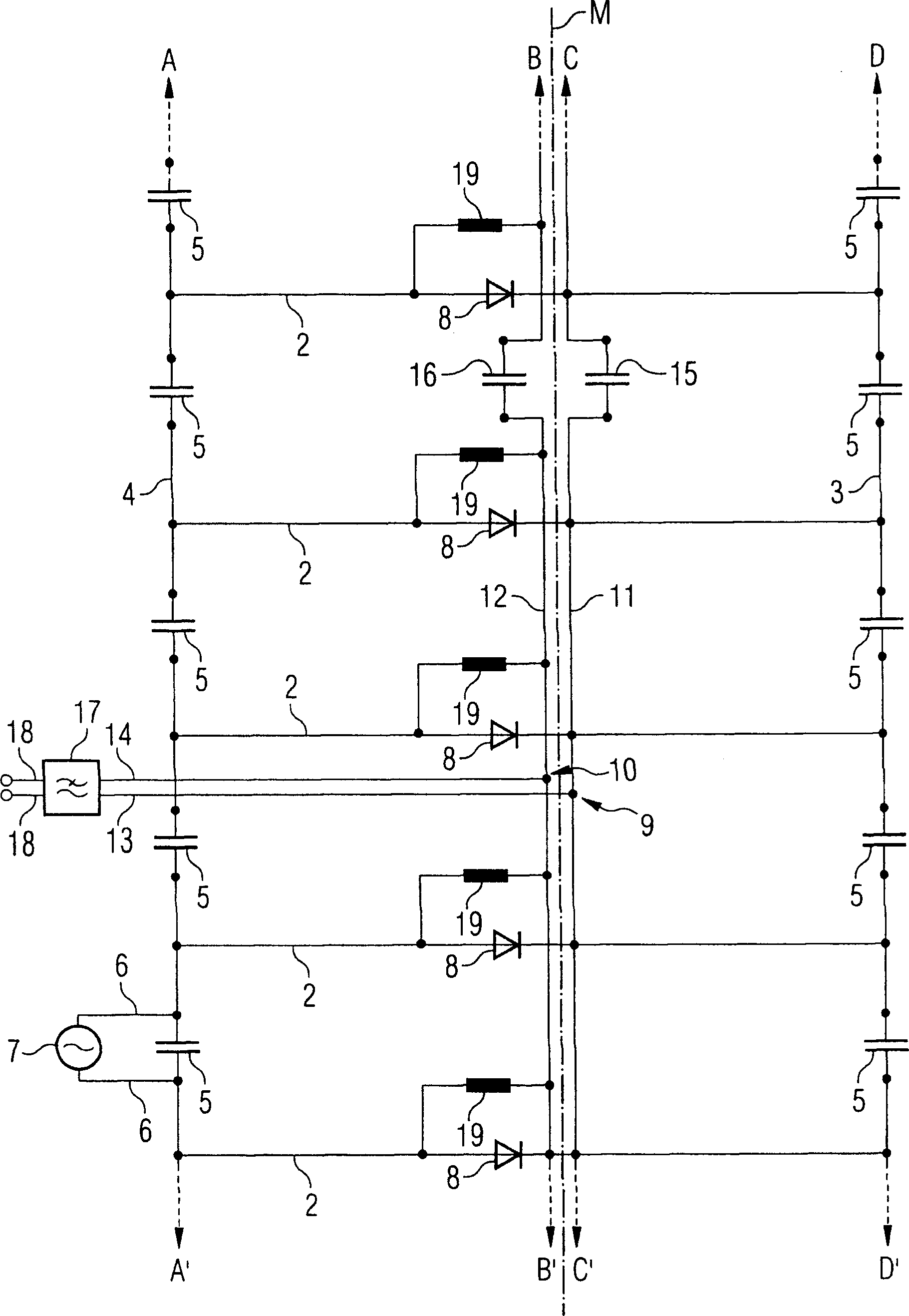
[0037] figure 1 The construction of a typical birdcage structure is shown in the form of a simple 3D wire model. Such a birdcage structure consists of several longitudinal rod antennas arranged on a cylindrical surface, equidistant and extending in parallel. These longitudinal rods are connected to each other at high frequency at the ends via antenna end rings 3 , 4 . “High-frequency connection” here means that no electrical connection is necessary, but only a transparent connection to high-frequency currents. Such as figure 1 As shown, also in the case of a birdcage-shaped magnetic resonance antenna, there is a resonant capacitor 5 in the antenna end ring between the connection points of two adjacent longitudinal rod antennas 2 . Here, for the sake of clarity, only the apparent overall structure of a hypothetical cylinder is shown, around which the wire model extends.

[0038] exist figure 1 In the embodiment shown, the end rings 3 , 4 are each circular. However, the en...


PUM


Abstract

A magnetic resonance antenna has longitudinal antenna rods in a birdcage structure, and antenna ferrules connecting the longitudinal antenna rods at their ends in terms of radio-frequency. The magnetic resonance antenna has a number of radio-frequency switching elements that interrupt, in terms of radio-frequency, at least one part of the longitudinal antenna rod to detune the eigen-resonance frequency of the antenna with respect to an operating magnetic resonance frequency. For this purpose, the magnetic resonance antenna is provided with two switching lines, directed to the radio-frequency switching elements from outside of the birdcage structure, the switching lines having a ring line connected thereto running annularly on or in the birdcage structure and transverse to the longitudinal antenna rods.

Description

technical field [0001] The invention relates to a magnetic resonance antenna. It has parallel longitudinal rod antennas arranged in a birdcage structure, and antenna end rings connected at high frequency to the ends of these rod antennas; and a plurality of high frequency switching devices, in order to make the inherent resonance of the antenna The frequency is detuned relative to the operating magnetic resonance frequency at high frequencies, disconnecting at least part of the longitudinal rod antenna. Background technique [0002] Modern magnetic resonance devices usually use a plurality of different antennas (hereinafter also referred to as coils) to emit high-frequency pulses for exciting nuclear resonance and / or to receive induced magnetic resonance signals. Usually, MRI equipment has a large so-called bulk coil (also called body coil, BC), which is usually fixedly installed in the equipment, and several small local coils (LC), also called surface coils . The role of...

Claims


Application Information

Patent Timeline
Patent Type & Authority Applications(China)
IPC IPC(8): G01R33/34G01R33/36
CPCG01R33/34046G01R33/3657
Inventor 路德维格·埃伯勒雷兹万·拉扎尔于尔根·尼斯特勒冈瑟·泽贝莱恩
Owner SIEMENS HEALTHCARE GMBH
Learn More