Optical scanning device, image display device provided with optical scanning device, retinal scanning display, and driving method of optical scanning element

a technology of optical scanning and image display, which is applied in the direction of medical science, diagnostics, instruments, etc., can solve the problems affecting the stability of the spring portion, and not having the oscillation frequency of the oscillating body. achieve the effect of increasing the oscillation frequency of the oscillating body

Inactive Publication Date: 2009-07-23
BROTHER KOGYO KK
View PDF7 Cites 11 Cited by
  • Summary
  • Abstract
  • Description
  • Claims
  • Application Information

AI Technical Summary

Benefits of technology

[0008]However, in allowing the optical scanning device to generate torsional oscillations by driving the spring portion of the optical scanning element, even when a drive signal having a frequency equal to the resonance frequency of torsional oscillations is applied to the optical scanning element, the oscillation frequency of the oscillating body does not promptly become equal to the resonance frequency of torsional oscillations, and the oscillation frequency of the oscillating body is gradually increased.

Problems solved by technology

However, in allowing the optical scanning device to generate torsional oscillations by driving the spring portion of the optical scanning element, even when a drive signal having a frequency equal to the resonance frequency of torsional oscillations is applied to the optical scanning element, the oscillation frequency of the oscillating body does not promptly become equal to the resonance frequency of torsional oscillations, and the oscillation frequency of the oscillating body is gradually increased.
When the subsidiary resonance oscillations continue and a considerable time is spent before the oscillation frequency of the oscillating body passes the resonance frequency of the subsidiary resonance oscillations, the spring portion may be damaged by the energy generated when the oscillation frequency of the oscillation frequency of the oscillating body passes the resonance frequency of the subsidiary resonance oscillations.

Method used


Image

  • Optical scanning device, image display device provided with optical scanning device, retinal scanning display, and driving method of optical scanning element
  • Optical scanning device, image display device provided with optical scanning device, retinal scanning display, and driving method of optical scanning element
  • Optical scanning device, image display device provided with optical scanning device, retinal scanning display, and driving method of optical scanning element

Examples


first embodiment

1. Explanation of the Whole Image Display Device 1

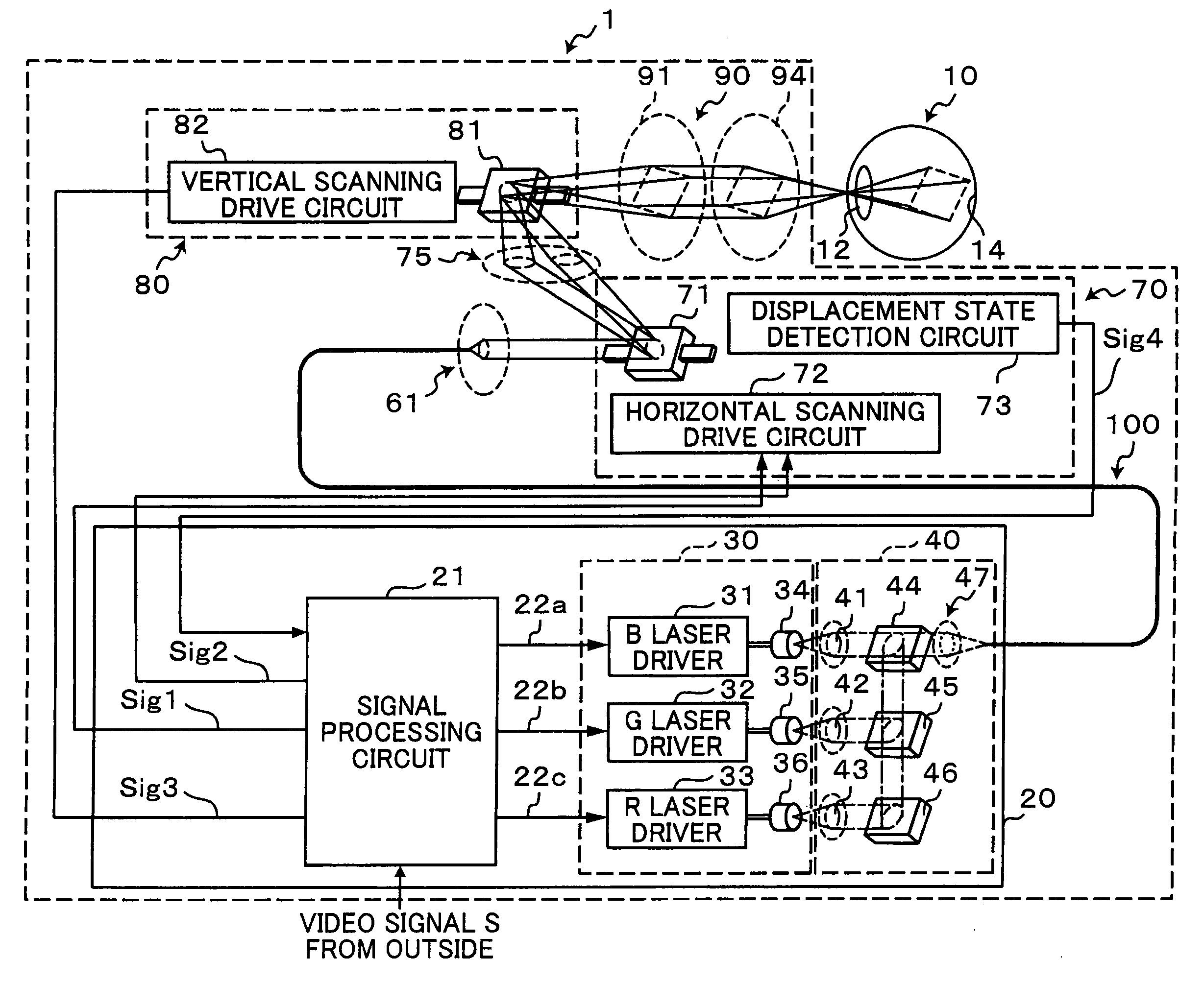
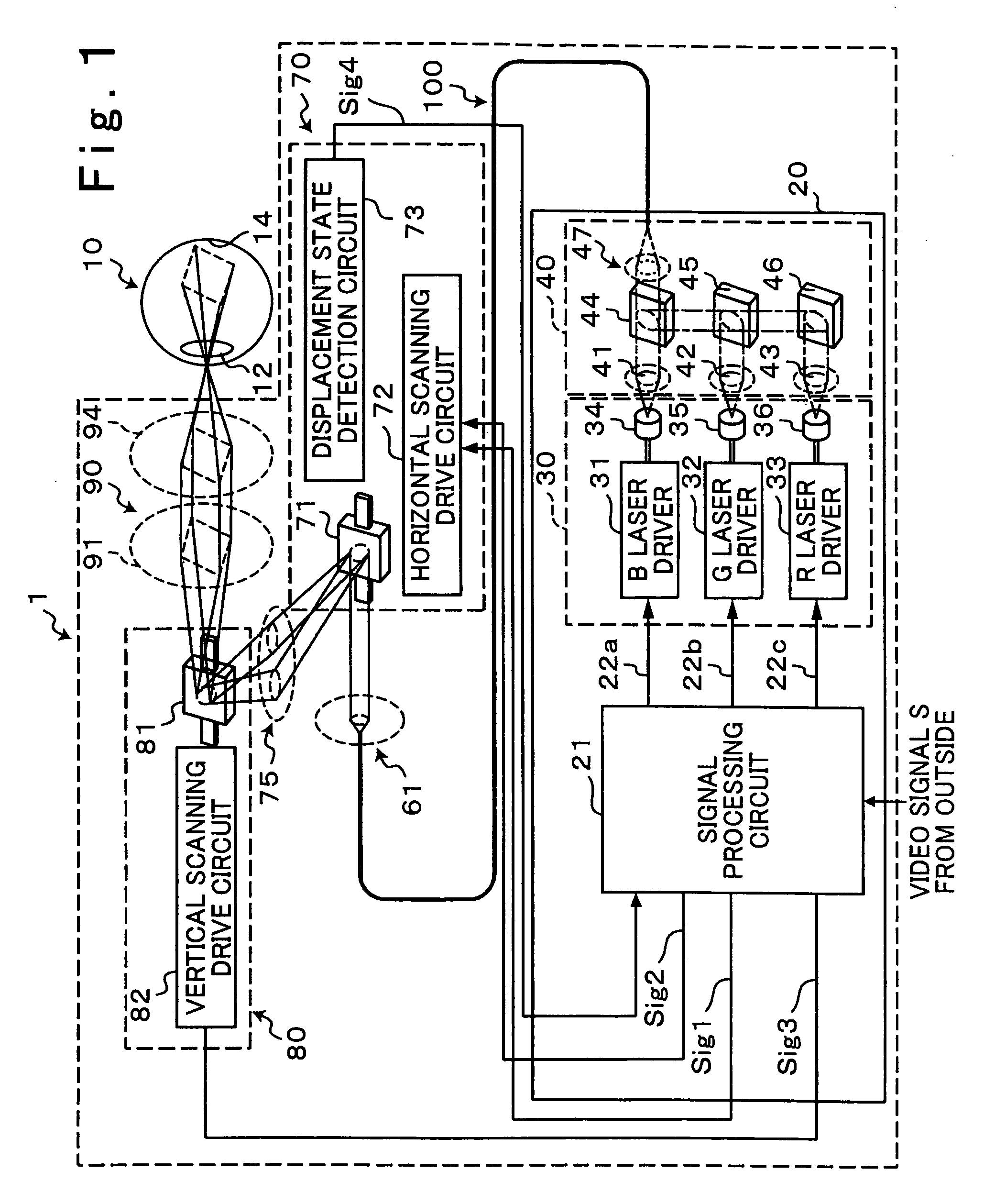
[0028]First of all, the whole constitution of an image display device 1 and the manner of operation of the image display device 1 are explained. FIG. 1 shows the whole constitution of the image display device 1 of the embodiment of the present invention. The image display device 1 is a retinal scanning display of a type which allows an optical flux to be incident on a pupil 12 of a viewer who is a user of the image display device 1 and projects an image on his / her retina 14. Due to such a constitution, the image display device allows the viewer to visually recognize a virtual image in front of the pupil 12 of a viewer's eye 10.

[0029]The image display device 1 includes an optical flux generator 20 which generates an optical flux (laser beams) whose intensity is modulated based on a video signal S supplied from the outside. Further, the image display device 1 includes, between the optical flux generator 20 and the viewer's eye 10, a co...


PUM


Abstract

An optical scanning element performs scanning with light by bringing a mirror portion into a swinging state by generating resonance oscillations of the mirror portion due to torsional oscillations. The optical scanning element has a first resonance frequency and a second resonance frequency which generate longitudinal oscillations and lateral oscillations on a lower region side and a high region side of a resonance frequency of the torsional oscillations respectively. Outputting of a drive signal is started by setting a frequency of a drive signal which is used for oscillating the optical scanning element to a specific frequency which falls between the first resonance frequency and the second resonance frequency and is higher than the resonance frequency of the torsional oscillations and, thereafter, the frequency of the outputted drive signal is shifted to the resonance frequency of the torsional oscillations after outputting of the drive signal is started.

Description

CROSS-REFERENCE TO RELATED APPLICATIONS[0001]The present application is a Continuation-in-Part of International Application PCT / JP2007 / 068374 filed on Sep. 21, 2007, which claims the benefits of Japanese Patent Application No. 2006-270130 filed Sep. 29, 2006.BACKGROUND[0002]1. Field[0003]The present invention relates to a technique for an optical scanning device, an image display device provided with an optical scanning device, a retinal scanning display, and a driving method of an optical scanning element, and more particularly to a driving technique for an optical scanning element.[0004]2. Description of the Related Art[0005]Conventionally, with respect to an optical scanning device which scans light, there has been known an optical scanning device which scans light using a resonance-type optical scanning element. With respect to the resonance-type optical scanning element, as described in JP-A-2005-275198, there has been known an optical scanning element which includes a mirror p...

Claims


Application Information

Patent Timeline
Patent Type & Authority Applications(United States)
IPC IPC(8): A61B3/10G02B26/10G09G3/00
CPCG02B26/105G02B26/0833
Inventor SAKAKIBARA, MASAHIRO
Owner BROTHER KOGYO KK
Why Eureka
Try Eureka