

Display capable of changing its direction
A technology to change the direction and display, which is applied to the direction of instruments, parts of instruments, support structures on hinges/pivots, etc., and can solve problems such as the limitation of display rotation angles
- Summary
- Abstract
- Description
- Claims
- Application Information
AI Technical Summary
Problems solved by technology
Method used
Image

Examples
no. 1 example
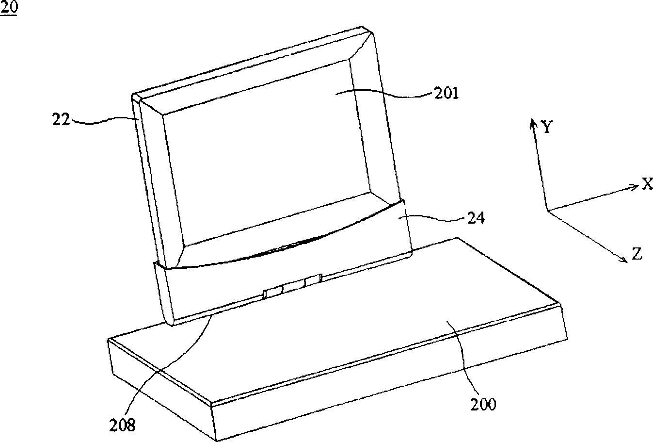
[0047] Figure 2a It is a schematic diagram of the front of the display panel of the direction-changing display according to the first embodiment of the present invention. The figure shows a notebook computer 20 (which may also be a desktop computer or other electronic products), which has the reversible display of the present invention. The notebook computer 20 shown in the figure is composed of a main body 200 , a base 24 , and a display panel 22 . The base 24 is rotatably connected to the main body 200 . The display panel 22 is detachably installed on the base 24 . In the figure, the front side 201 of the display faces the +Z direction (the first direction), while the back side 202 of the display faces the −Z direction (the second direction), and the first direction is opposite to the second direction. The display panel 22 can be selectively mounted on the base 24 facing the first direction or the second direction. The direction-changing display of the present invention...
no. 2 example
[0059] The second embodiment is substantially the same as the first embodiment, Figure 3a It is a schematic view of the front of the display of the second embodiment of the present invention which can change the direction of the display. The figure shows a notebook computer 20 (or a desktop computer or other electronic products), including a main body 200 , a base 24 , and a display panel 22 . The difference between the second embodiment and the first embodiment is that the groove 36 is provided on the display panel 22, and the base 24 includes a protrusion 38, such as Figure 3b shown. The display panel 22 is installed on the base 24 by inserting the protruding portion 38 into the groove 36 . The continuous action of changing the orientation of the display panel in the second embodiment of the present invention is found in Figure 3a to Figure 3d , the operation of the conversion panel is the same as that of the first embodiment, so the description is omitted.
[0060] s...
no. 3 example
[0066] The third embodiment is substantially the same as the first and second embodiments, see Figure 4 , Figure 4 It is a schematic diagram of wires of the direction-changing display according to the third embodiment of the present invention. In the figure, the same elements as those of the first and second embodiments are assigned the same numbers, and their descriptions are omitted. The third embodiment of the present invention also includes a wire 210. When the display panel 22 is separated from the base 24, one end of the wire 210 is connected to the first connector 203, 303, and the other end is connected to the second or third connector. Therefore, the display panel 22 and the base 24 can be connected through the wire 210 , and the length of the wire can be determined by the user or the manufacturer. In this way, the display panel 22 is not limited by the position of the host 200 and can be placed or rotated freely.
PUM
 Abstract
Description
Claims
Application Information