
Blanking mould and manufacturing method thereof

A manufacturing method and technology of blanking dies, applied in cleaning methods and tools, chemical instruments and methods, cleaning methods using gas flow, etc., can solve problems such as reducing productivity and increasing manufacturing processes

Inactive Publication Date: 2004-10-20
TAKAHASHI KEISEI
View PDF0 Cites 4 Cited by
  • Summary
  • Abstract
  • Description
  • Claims
  • Application Information

AI Technical Summary

Problems solved by technology

[0009] In the punching process of a sheet, a method of removing the punching gas by suction from above with a blower and blowing of compressed air in the process after punching has been proposed (refer to Patent Document 2), but there are still problems due to increasing The manufacturing process is simplified, so problems such as productivity are reduced

Method used


Image

  • Blanking mould and manufacturing method thereof
  • Blanking mould and manufacturing method thereof
  • Blanking mould and manufacturing method thereof

Examples


Embodiment Construction

[0075] Hereinafter, the first punching die of the present invention will be described in detail with reference to the drawings, but of course, the interpretation of the present invention is not limited by the following description.

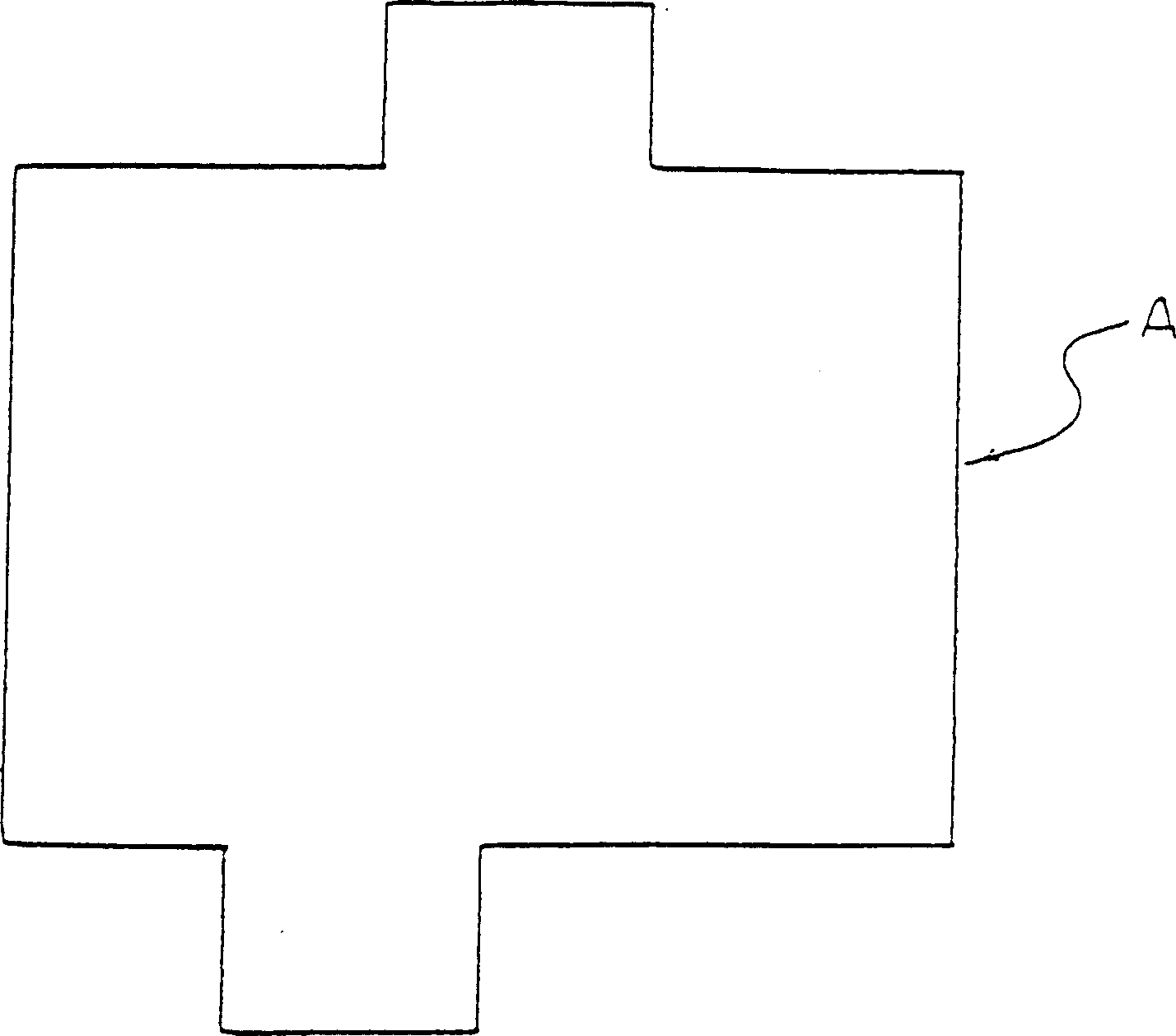
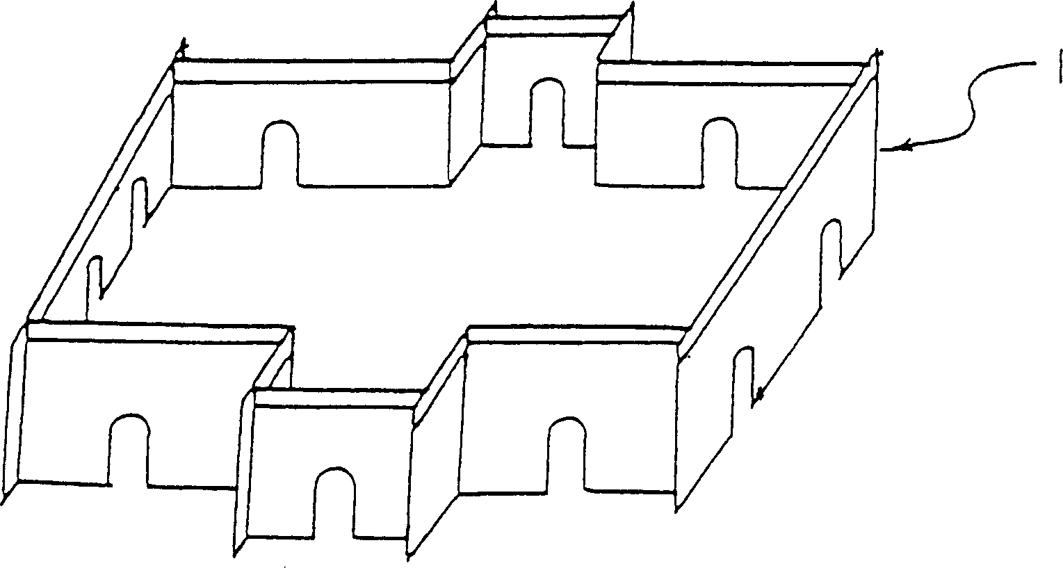
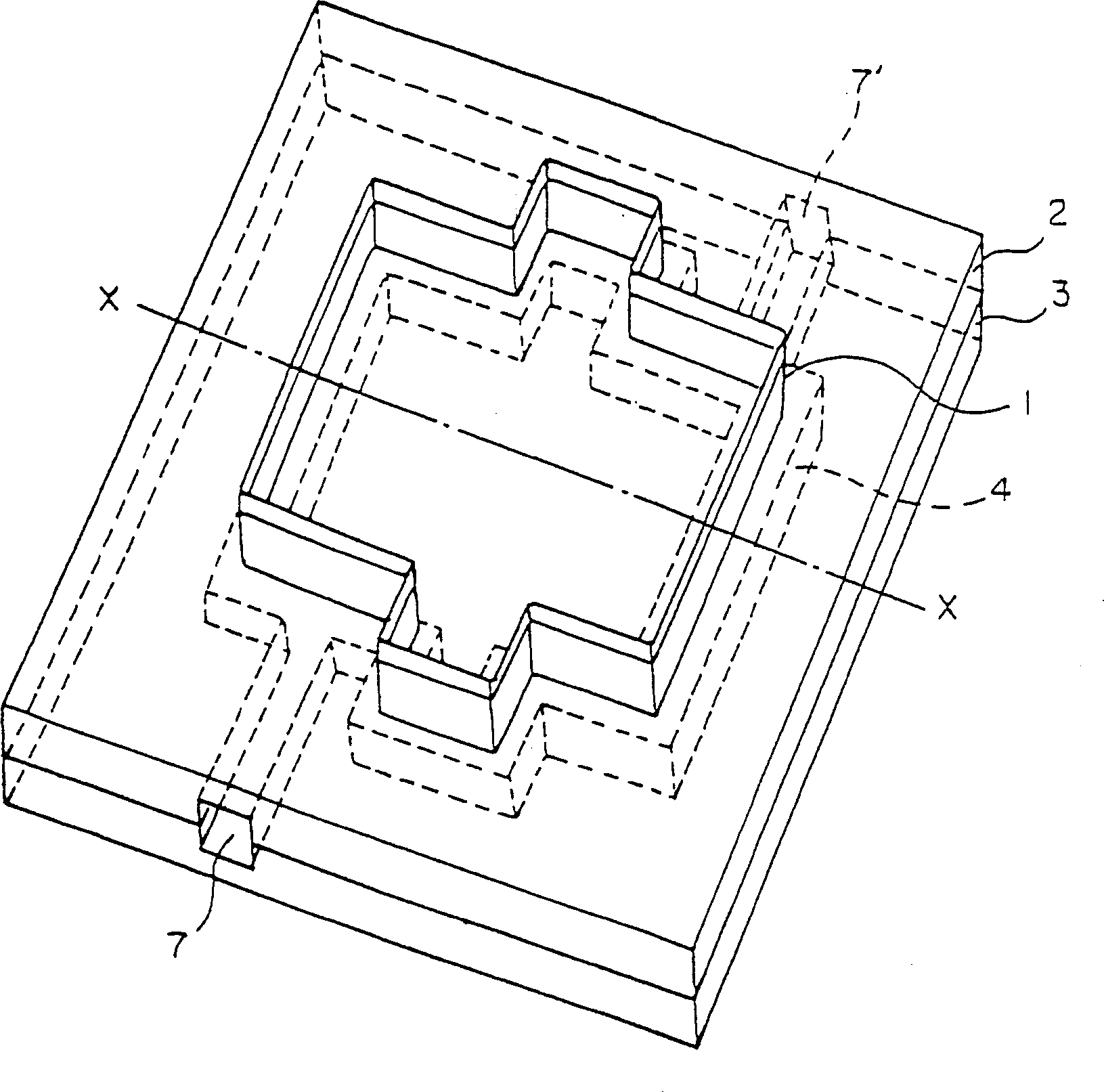
[0076] figure 1 In order to show a view of a sheet being punched out in an example of the punching die of the present invention, figure 2 It is a perspective view of a cutting blade (an example having a concave portion) set in a desired shape before being inserted into the punching die of the present invention, image 3 To show the perspective view of the first blanking die of the present invention, Fig. 4 (a) is the perspective view of the base material 3 on the lower side, Fig. 4 (b) is the perspective view of the base material 2 on the upper side in an inverted state, and Fig. 5 ( a) for edge image 3 Figure 5(b) and Figure 5(c) are cross-sectional views of other shape examples of the resin filling chamber.

[0077] exist image 3 ~ In Fi...


PUM


Abstract

Provided is a blanking die which causes no slack of a fixed punch and carries out exact blanking even if a large number of sheetlike materials are blanked at a high speed, and also to provide a blanking die which easily separates products obtained by blanking the sheetlike materials from the scraps, and causes no pollution problems even if the disposal by incineration is carried out. Base materials 2, 3 of the blanking die have spaces 4 surrounding the punch 1. Resin is charged into the spaces and is solidified to fix the punch 1. Further, the spaces 4 are filled with gas, and the base material 2 is provided with a plurality of gas flowing-out holes. As a result, the products and the scraps are easily separated by flowing-out the gas through the gas flowing-out holes.

Description

technical field [0001] The present invention relates to a punching die for punching a sheet-like material such as a plastic plate or a corrugated cardboard into a desired shape and a method for manufacturing the punching die. technical background [0002] A conventional punching die will be described with reference to the drawings. [0003] Figure 19 To show a perspective view of a conventional punching die, Fig. 20(a) is the edge of a thin groove formed using a laser beam. Figure 19 Y, the enlarged cross-sectional view of the Y line, Figure 20(b) is the edge when using end mills and steel wires to form fine grooves Figure 19 Y, Y-line zoomed-in profile. Conventionally, as a punching die for punching a sheet-like material such as a plastic plate or a corrugated cardboard into a desired shape, a plate-shaped body (referred to as a "base material" in this specification) made of wood such as a veneer, for example, has been used. A base material 2 composed of a plywood, a pl...

Claims


Application Information

Patent Timeline
Patent Type & Authority Applications(China)
IPC IPC(8): B26D7/26B26F1/44
CPCB08B5/02B26D7/1863B26D7/2614B26D9/00
Inventor 高桥光广
Owner TAKAHASHI KEISEI
Learn More