Display device
A display and display panel technology, applied in instruments, nonlinear optics, optics, etc., can solve problems such as innovation and improvement of liquid crystal display
- Summary
- Abstract
- Description
- Claims
- Application Information
AI Technical Summary
Problems solved by technology
Method used
Image

Examples
Embodiment Construction
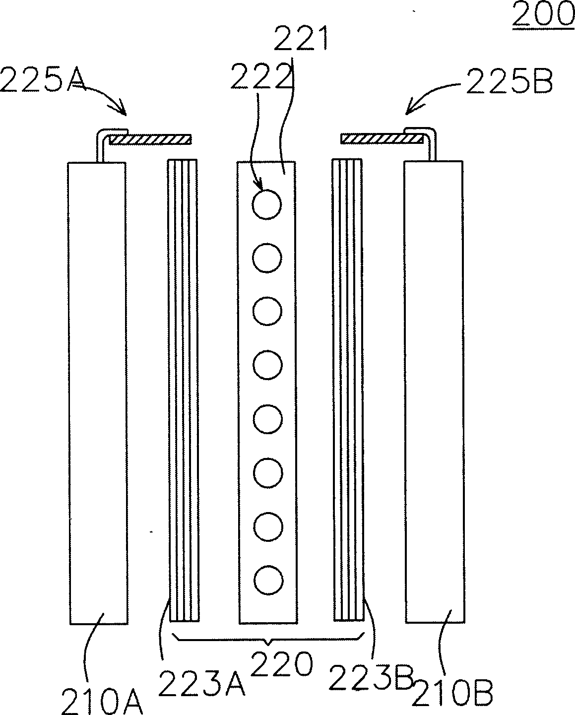
[0012] Please refer to figure 2 , which is a schematic cross-sectional view of a liquid crystal display according to a preferred embodiment of the present invention. The liquid crystal display 200 includes two display panels 210A and 210B, and a direct-lit backlight assembly 220 . The display panel 210A and the display panel 210B are opposite to each other, and the direct type backlight assembly 220 is disposed between the display panels 210A and 210B. The direct type backlight assembly 220 includes two optical films 223A and 223B, a plurality of light sources 222 and a lamp holder 221 . The lamp holder 221 is used to place the light source 222, and the light source 222 is, for example, several cold cathode tubes, which are linearly arranged in the lamp holder 221 to provide uniform and sufficient light for the display panel 210, so as to perform a better display. like quality. The optical film 223A is disposed between the light source 222 and the display panel 210A, and i...
PUM
 Abstract
Description
Claims
Application Information
PatSnap Eureka turns technology decisions into work you can execute. Powered by our Innovation Knowledge Graph, it runs expert workflows across engineering, life sciences, materials and intellectual property. Get your review-ready output in minutes.


