
Light negative module and liquid-crystal displaying device

A liquid crystal display and backlight module technology, applied in the directions of instruments, optics, light guides, etc., can solve the problems of complicated production of color filter films, low price, and increased complexity of color filters.

Inactive Publication Date: 2007-02-07
AU OPTRONICS CORP
View PDF5 Cites 0 Cited by
  • Summary
  • Abstract
  • Description
  • Claims
  • Application Information

AI Technical Summary

Problems solved by technology

[0011] However, since the production of color filter films is relatively complicated and the price is not cheap, the overall price of liquid crystal displays cannot be further reduced.
In addition, since the color filter film and the black matrix on the substrate are often unevenly arranged, the color filter must be covered with a flat layer on the color filter film and black matrix during the production process. (over coating) to achieve the purpose of surface flattening, which will increase the complexity of color filter production, and is also a burden on cost
In addition, since most of the current liquid crystal displays use a color filter substrate and a thin film transistor array substrate to sandwich the liquid crystal layer between the two, this design structure will limit the development of the miniaturization of liquid crystal displays

Method used


Image

  • Light negative module and liquid-crystal displaying device
  • Light negative module and liquid-crystal displaying device
  • Light negative module and liquid-crystal displaying device

Examples


Embodiment Construction

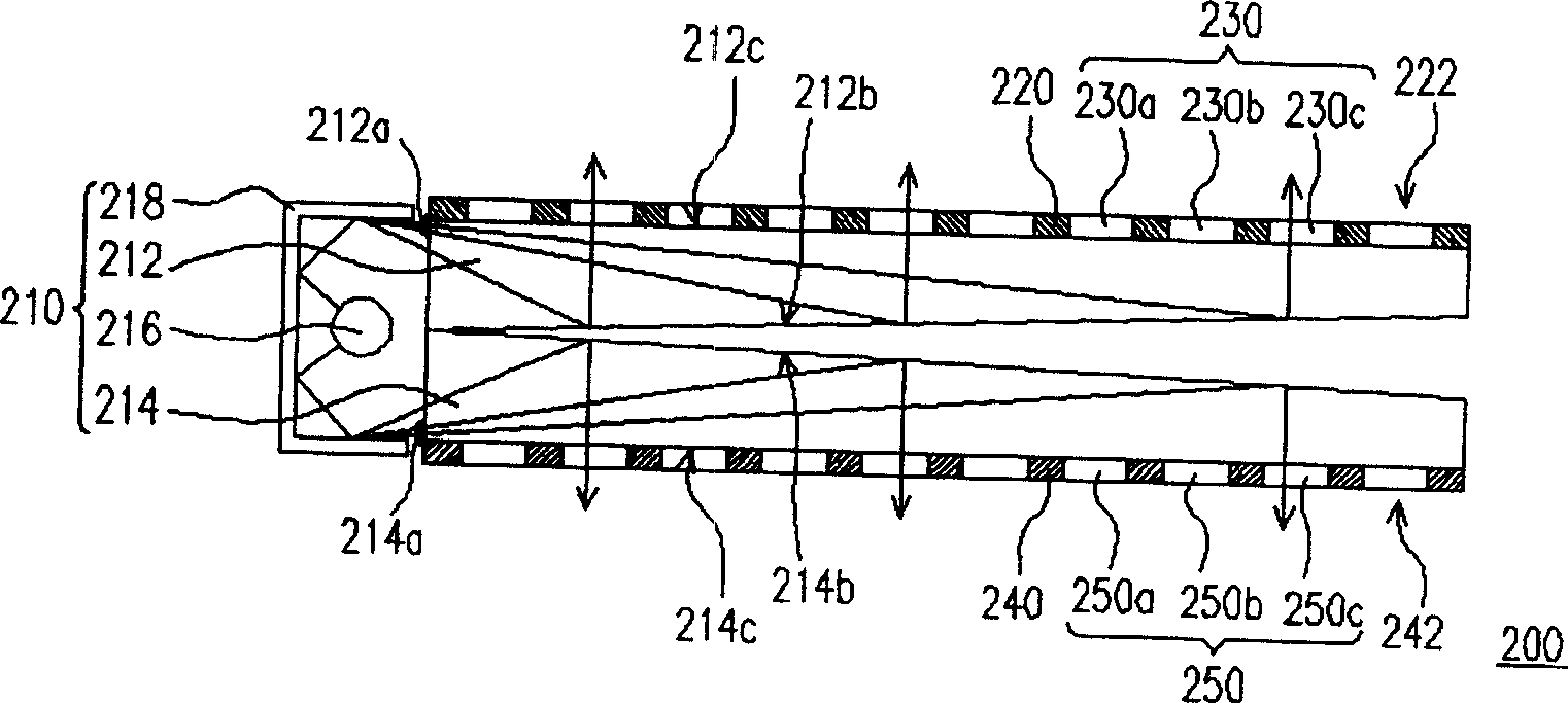
[0092] figure 2 It is a structural schematic diagram of a backlight module in a preferred embodiment of the present invention. Please refer to figure 2 As shown, the backlight module 200 is mainly composed of a surface light source 210 , a first shading matrix 220 , a second shading matrix 240 , a first fluorescent layer 230 and a second fluorescent layer 250 .

[0093] Such as figure 2 As shown, the surface light source 210 is composed of a first light guide plate 212 , a second light guide plate 214 , a line light source 216 and a reflector 218 . Wherein, the first light guide plate 212 can be a wedge-shaped light guide plate, the first light guide plate 212 has a first light incident surface 212a, a first light diffusion surface 212b and a first light exit surface 212c, and the first light diffusion There are a plurality of V-shaped notches on the surface 212b (visible at the area A in the figure), and the second light guide plate 214 has the same structure as the fir...


PUM


Abstract

A module on own light is composed of face light source, the first shading matrix, the second shading matrix, the first fluorescent layer and the second fluorescent layer of which the two shading matrixes are set on two outer surfaces of the face light source and equipped with multiple lattice point exposed out of two outer surfaces on face light source, the two fluorescent layers are set in these lattice points correspondingly. The two fluorescent layers are used to achieve colouring aim for the light transmitted from two outer surfaces of the face light source. The liquid crystal display provided by the present invention is composed of above module on own light, two polarized light film, two electrode layers, two digit group base plates and two liquid crystal layers.

Description

technical field [0001] The present invention relates to a back light module (Back Light Module) and a liquid crystal display (Liquid Crystal Display, LCD), and in particular to a back light module suitable for providing colored double-sided light sources and a liquid crystal display using the back light module. Background technique [0002] In order to adapt to the modern life style, the volume of video or image devices is becoming thinner and thinner day by day. Although the traditional cathode ray display (CRT) still has its advantages, due to the structure of the internal electronic cavity, the display is bulky and takes up space, and there are still problems such as radiation damage to the eyes when displaying. Therefore, flat panel displays developed in conjunction with optoelectronic technology and semiconductor manufacturing technology, such as liquid crystal displays (LCDs), organic light emitting displays (OLEDs) or plasma displays (Plasma Display Panels, PDPs), hav...

Claims


Application Information

Patent Timeline
Patent Type & Authority Patents(China)
IPC IPC(8): G02F1/13357F21V8/00G02F1/1335H01J61/00
Inventor 庄信源张哲誌
Owner AU OPTRONICS CORP
Features
  • Generate Ideas
  • Intellectual Property
  • Life Sciences
  • Materials
  • Tech Scout
  • Unparalleled Data Quality
  • Higher Quality Content
  • 60% Fewer Hallucinations
Learn More