Eureka AIR delivers breakthrough ideas for toughest innovation challenges, trusted by R&D personnel around the world.

High impedance isolation device in signalling monitoring system

A monitoring system and high-resistance isolation technology, applied in transmission systems, selection devices, line transmission monitoring/testing, etc., can solve problems such as inability to transmit far, large signal loss, and easy oscillation, so as to extend transmission distance and improve high performance. resistance performance, reducing the effect of current shunt

Active Publication Date: 2004-10-20
ZTE CORP
View PDF1 Cites 3 Cited by
  • Summary
  • Abstract
  • Description
  • Claims
  • Application Information

AI Technical Summary

Problems solved by technology

In the prior art, the patent XXXXXXX (application number 00235433.0) applied by XXXX proposes a high-resistance isolation device, such as figure 2 As shown in , the high-impedance isolation device includes a coupling coil T1 and two resistors R1, R2. The signaling signal is introduced from the left end of the isolation device to the original end of the coupling coil T1, coupled through the coupling coil T1, and passed through the coupled output terminal. The two resistors R1 and R2 are output to the data acquisition equipment of the monitoring system. This device can isolate the signal and reduce the impact of the monitoring system on the monitored system, but there are still the following disadvantages: ①. The coupling coil is an inductive coil , belongs to the inductive load, which is directly connected to the monitored system, causing the phase shift of the monitored signal, and the collected signal is prone to problems such as oscillation, offset, and waveform deformation; ②, the high-impedance design is at the output end of the coil. Once a process failure such as a short circuit occurs at the input end, it is easy to cause the interruption of the measured link; ③, the signal is output from the coupling device to the acquisition device of the monitoring system through two resistors R1 and R2, after passing through the transmission line, the signal loss is large and cannot be transmitted remotely , the farthest transmission distance of this technology is only 150 meters, in addition, it will also have a negative impact on the bit error rate of the acquisition system

Method used


Image

  • High impedance isolation device in signalling monitoring system
  • High impedance isolation device in signalling monitoring system
  • High impedance isolation device in signalling monitoring system

Examples


Embodiment Construction

[0011] The present invention will be further described in detail below in conjunction with the accompanying drawings and embodiments.

[0012] figure 1 and figure 2 It has already been explained in the background art.

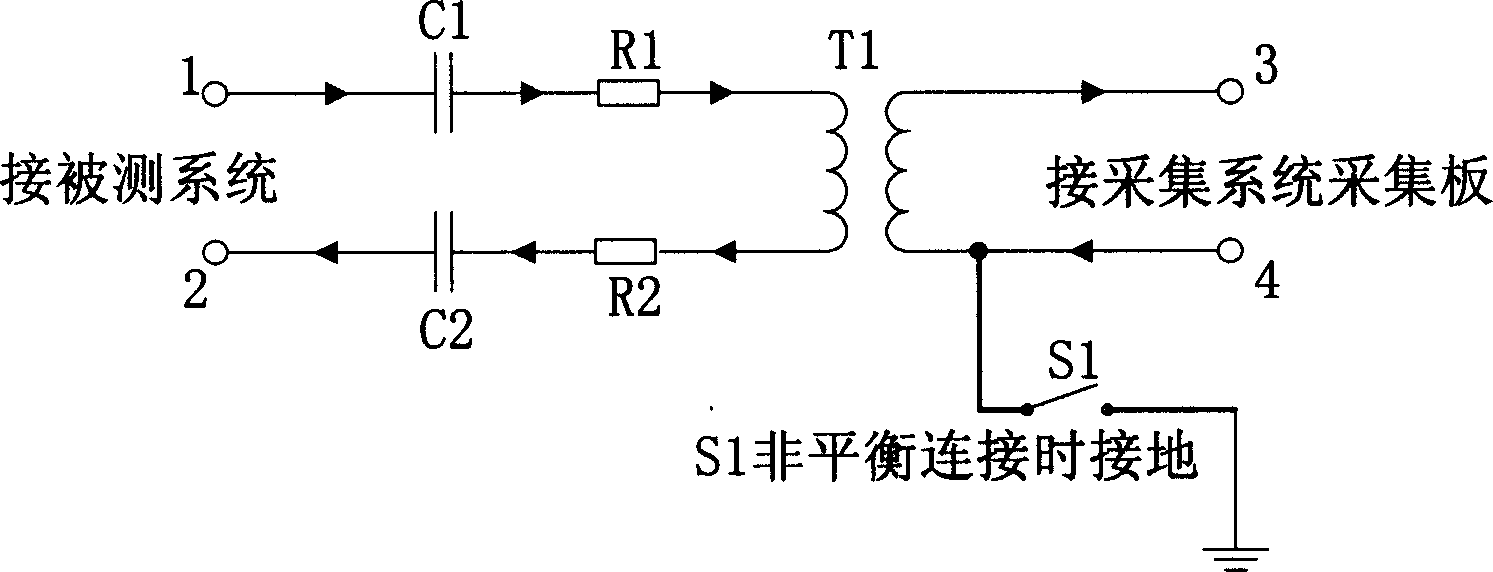
[0013] image 3 It is a schematic structural diagram of the high-resistance isolation device proposed by the present invention. like image 3 As shown, the high-impedance isolation device proposed by the present invention includes a coupling coil T1, two resistors R1 and R2 with the same resistance value; and two capacitors C1 and C2 with the same capacitance value; one end of the capacitor C1 is connected to the measured system, the other end is sequentially connected in series with the resistor R1, the positive and negative poles of the original terminal of the coupling coil T1, the resistor R2, and the capacitor C2, and then connected to the system under test; the positive and negative poles of the coupled output terminal of the coupling coil T1 are con...


PUM

PropertyMeasurementUnit
Resistance valueaaaaaaaaaa
Capacitanceaaaaaaaaaa

Abstract

The device includes a coupling coil T1, two identical resistances R1 and R2 as well as two identical capacitors C1 and C2. One end of the C1 is connected to system to be measured, and after connecting to R1, positive and negative ends at primary side of T1, and R2, C2 in sequence, the other end of the C1 is connected to system to be measured. Positive and negative ends of coupled output end of T1 are connected to collecting device. The invented device also includes a switch between negative end of coupled output end and ground. The switch is on if output end in 75 ohm, and the switch is off if output end in 125 ohm. the advantages are obstructing influence on original signal, improving waveform of collected signal, avoiding short circuit etc.

Description

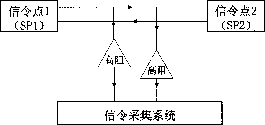
technical field [0001] The invention relates to a signaling monitoring system, in particular to a collection and isolation device in the signaling monitoring system. Background technique [0002] The signal acquisition of the signaling monitoring system comes from the signaling link of the monitored system. At present, the commonly used method is to use a high-impedance isolation device to bridge the monitored signaling link, and the induction signal obtained through the high-impedance isolation device , as the input signal of the monitoring system. Due to the introduction of the monitoring system, the signal of the original signaling link will be shunted to the monitoring system, and the signal amplitude will be reduced. figure 1 It is a schematic diagram of the principle of an existing signaling system signal acquisition device. like figure 1 As shown, there are two signaling links between signaling point 1 (SP1) and signaling point 2 (SP2). On the command link, the in...

Claims


Application Information

Patent Timeline
IPC IPC(8): H04B3/46H04B7/26
Inventor 周文瑞刘燕花茂盛曾玉松
Owner ZTE CORP
Why Eureka
Eureka Blog
Learn More